Featured Post

Beolover SyncDrive: DC Platter Motor Replacement for Beogram 4002 and 4004 (Type 551x and 552x)

Late Beogram 4002 and the 4004 (Types 551x and 552x), which have DC platter motors instead of the earlier synchronous AC motors usually suff...

Showing posts with label voltage. Show all posts

Thursday, June 1, 2017

Beogram 8000: Completing the Capacitor Replacement and Checking the Work

Today I finished up the capacitor replacement by changing out the motor capacitor in the transformer box and the 5VDC power regulator capacitors on the chassis.

Here is the motor coil coupling capacitor located in the transformer box and its Beolover 3D printed part replacement.


Very nice and tidy (and secured).
Next were the capacitors for the chassis mounted 5V regulator.


Now for a quick test to see where this restoration is at. The first thing to check is the +5V power to the microcomputer. I measured the voltage across the new C28 capacitor in the microcomputer board. This is why I haven't close up that board assembly yet.


Processor supply power looks good and the Beogram 8000 red standby dot illuminated in the speed display window.

Now to check the platter speeds. When this turntable first arrived I did a quick check to see if there was anything noticeably wrong. I remember that the 45 RPM appeared to work but the Beogram was having problems locking in the 33.33 RPM speed.  After the capacitor rework I wanted to check the speeds again.

Both speeds lock right in when selected now.


Those were good test results after the capacitor replacements.  There are still quite a few tasks remaining though. I need to run through the mechanical adjustments and there are several electrical adjustments/checks to do.

Thursday, September 10, 2015

Beogram 4000: Adjusting the AC Motor Voltage and Measuring the Voltage Differences Between the Phases

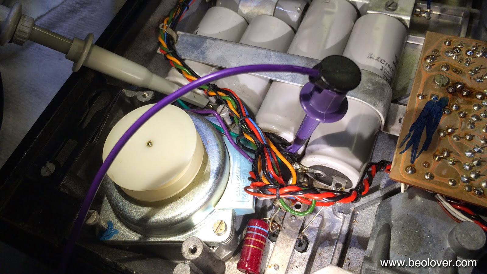
Today I adjusted the AC motor of the Beogram 4000 that I am currently restoring. The manual prescribes to adjust the main phase of the motor to 6V (RMS) and the frequency to 42.3 Hz for 33 RPM. This is easily done with an oscilloscope. To see both phases the probes can be simply connected to either side of the phase capacitor:

Adjustment procedure: First set the 33 RPM trimmer on the control panel to its null position (i.e. vertical). This ensures that the adjustment of the RPM offset potentiometer on the main PCB can now be adjusted to yield a 42.3 Hz motor signal when the control panel trimmer is nulled out. This ensures that the user can both trim the pitch for the same frequency deviations in + and - directions. Once the frequency is set the MOT potentiometer can be adjusted. It is important to do it in this order, since the frequency affects the amplitude of the signal. We are working with an analog oscillator here...;-).
Once everything is adjusted the oscilloscope should show about this:

The yellow trace is the main phase and the green trace is the 2nd phase. It is interesting to note that the 2nd phase has a smaller 5.3V (RMS) amplitude. This concludes the adjustment.

When switching the motor to 45 RPM one sees this:


Note that the 2nd phase is now much larger, about 8V (RMS), while the main phase dropped a bit to 5.6V (RMS). The manual also wants 6V (RMS) here, but there is nothing one can do about this since the MOT trimmer determined both frequencies, and 33 RPM is probably for most people the much more important speed. 

There is an interesting detail I noticed about the RPM trimmers on the control panel. The 45 RPM trimmer is nulled when the correct frequency of 57.3 Hz is adjusted with it:


When I took the control panel apart for converting it to LED illumination, I noticed that the red inserts that allow the adjustment of the trimmers with a screw driver are different for 33 RPM and 45 RPM: The driver slot is at an off-angle for the 45 potentiometer, while for the 33 trimmer it is symmetrical. Again, the designers gave the 33 speed priority and made a small compromise for 45: The consequence of this off-angle is that the 45 speed can only be adjusted by about a quarter turn to higher speeds, while one can go about a half turn to lower speeds. All this was probably dictated by the need for using standard resistors and trimmers in the Wien oscillator feedback circuits, which prevented them from designing the circuit in a way that the 45 trimmer would be exactly in its center position for an exact 57.3 Hz.
With modern resistor values one could easily fix this since nowadays one can buy resistors with almost any value. Apparently not so in 1973. Of course if one would now fix this by replacing the resistors, the trimer slot would be at an angle, which would not look good. What a conundrum! Will I be able to sleep tonight?? This is Beolove!..;-)


Monday, April 27, 2015

Beogram 4000: Adjusting the AC Motor Voltage

When I initially tested the Beogram 4000 that I am currently restoring, I noticed that the motor was running a bit noisy, especially at 45 RPM. After I replaced all the electrolytic capacitors, this got better, but did not go fully away. So it was time to look into the motor voltage and the waveform that is presented to it by the Wien bridge oscillator (a nice classic design including the amplitude control light bulb that acts as a variable resistor that increases its resistance as the current increases - pretty nifty!). The AC waveform amplitude can be measured at one of the motor leads relative to GND.

This shows how I hooked up the oscilloscope probe between the 150uF unipolar phase shift capacitor for the 2nd phase of the motor and the 4000uF coupling capacitor to the motor drive amplifier (the purple clip makes the GND connection conveniently using the negative pads of the 3000uF reservoir caps):

The GND connection was made at the negative ends of the 3000uF reservoir caps. This is what I found at 33 RPM:


The RMS voltage was at 7.9V and the signal was clipped. A clear case of overdriving. 45 RPM looked like this: 

Per service manual, the drive is to be adjusted to a RMS voltage of 6.5V at 33 RPM. I switched back to 33 RPM and turned the MOT potentiometer on the main circuit board until I saw a perfect waveform at 6.5V:


I also adjusted the "33" RPM trimmer (to the right of the MOT trimmer) until I got the specced frequency of 42.3 Hz.

An issue of this design is that 45 and 33 RPM have the same MOT trimmer setting but the oscillator puts out different amplitudes. Hence there is a small difference in the drive amplitude at 45 when the adjustment is made at 33:


There is also a small amount of distortion. This can easily be reduced if the drive voltage is reduced a bit to 5.5V:

But of course this results in a too low 33 RPM voltage of only 5.8V RMS at this setting:

I guess the designers elected to live with this small imperfection, since 45 is not so important historically. It also should be noted that the motor runs now very quietly at 45 despite the slight distortion and too low voltage. In light of the new 45 RPM audiophile vinyls, of course, one might consider getting a second 4000 adjusted perfectly for 45 RMP...;-).