Featured Post

Beolover SyncDrive: DC Platter Motor Replacement for Beogram 4002 and 4004 (Type 551x and 552x)

Late Beogram 4002 and the 4004 (Types 551x and 552x), which have DC platter motors instead of the earlier synchronous AC motors usually suff...

Showing posts with label output transistors. Show all posts

Wednesday, October 28, 2020

Beomaster 2400 Type 2902 - Canada Project Power Supply & No-Load Current Adjustment

 The hard parts of the Beomaster 2400 are completed. It is time to put the receiver back together so I can do some basic voltage checks.  

First though I need to re-attach the four output amplifier transistors that mount to the Beomaster 2400 heat sinks. I like using the Sil-Pad thermal interface product rather than the white thermal paste in these low profile receivers. The Sil-Pads do a good job and don't have the mess that paste does.


At this point I decided I wanted to check the Beomaster 2400 restoration I had done so far by powering up the Beomaster and performing some basic service manual tests.  In order to do that I re-attached the Filter & Tone Control board along with the Beomaster 2400 lamp boards.


If you think your eyes are playing tricks on you in the above two photos they are not. I didn't really like the new replacement 2C92 2200uF, 25V capacitor for +15VDC in the Beomaster.  The markings on that capacitor were kind of strange. It wasn't as clear as it should be about which end of the axial capacitor was positive and negative. Normally the (-) marking is a distinct arrow pointing at the negative end. This capacitor looks like it points in both directors and the data sheet on it wasn't any help...so I switched it out with a Vishay 2200uF, 25V, axial capacitor that has clear polarity markings.

Plugging in the Beomaster 2400 and turning the master power switch on resulted in the red Standby LED illuminating.

The first test I performed was for the +15VDC supply. I adjusted it to the required +15V per the service manual.


Next were the left and right channel no-load current adjustments.
The space for attaching measurement wires and adjusting the trimmers is very cramped in the Beomaster 2400. My method of performing the adjustment is to mount the measurement wires across the emitter resistors from the bottom of the Beomaster 2400 main board.


That provides the leads I need to attach my DMM for the no-load current measurements.
I adjusted the left channel for the target 12mV across the emitter resistor test points.


Then I adjusted the right channel.


So far everything looks good.

I want to measure the Beomaster 2400 muting circuit while I have the cover off and the original lamps still attached. That is the volume muting that occurs when the music source is switched.  Pressing one of the Beomaster music source switches should send a volume mute signal to the volume control until the source switching is completed.

I soldered on some test wires so I can watch the muting circuit in action with an oscilloscope.


Tomorrow I will measure what goes on with the volume muting circuit.

Thursday, February 14, 2019

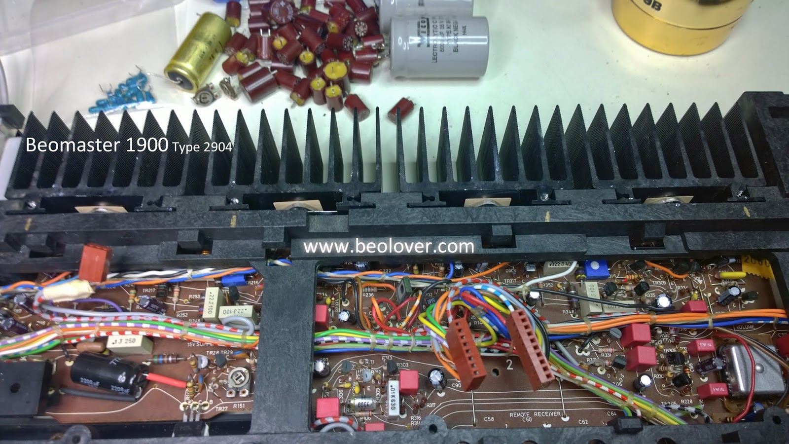
Beomaster 1900 Type 2904: New idle current trimmers and output transistor thermal insulators

I started to work on replacing the electrolytic capacitors on the last board, the tone control and FM tuning control board. Unfortunately I ran out of my favorite 2.2uF WIMA capacitors. There is a Mouser distribution center close to me however so the parts will arrive tomorrow.

In the meantime I will go ahead and change out the left and right channel 250Ω trimmer resistors that are used to adjust the output amplifier no-load current. Now is a good time to change them.

Here are pictures of the trimmer replacements.


Along with that change I cleaned off the old, dry thermal insulation paste on the four output transistors that are mounted on heatsinks in the back of the Beomaster. I like replacing that with new Sil-Pad thermal insulators.


Here are the heatsinks reinstalled.


Monday, February 20, 2017

Beomaster 8000: Left Channel Output Amplifier Rework Complete

I finished reworking and retesting the Beomaster 8000 left channel output amplifier last night.
Here is everything ready to begin the reassembly. There was the matter of replacing the TR208 transistor that had the cracked case. Luckily I found a spare BD165S transistor.


This time, from lessons learned on the right channel reassembly, I am starting the reinstall of the components to the heatsink from the bottom up. Here is the sequence.


After that was IC205, IC206 then the left row of components also from the bottom up.


From there is was back to the bench test to check out the board and re-adjust the no-load idle current.


Everything tests out good so now I will re-install the board into the Beomaster and re-run the burn-in test. Unfortunately the left side of the Beomaster makes it too difficult to install the output amplifier assembly all connected up. At least I haven't figured out a way to do it. So I will have to un-solder the heatsink assembly wires from the board, then re-solder them once I get the heatsink remounted to the chassis.

Saturday, February 18, 2017

Beomaster 8000: Left Channel Output Amplifier Heatsink Components Rework

I started looking at the Beomaster startup circuit relays but the left channel output amplifier assembly was on my mind. I just reworked the right channel output amplifier heatsink components and had found the TR208 transistor loose. Several of the TIP141/146 transistors had mica insulators that weren't in very good shape.

The restoration of the right channel looked pretty good to me so I really wanted to do the left channel even though it appeared to be working fine. This is a restoration project so I pulled the left channel amplifier assembly.

I am glad I did. The left channel TR208 had shifted badly. It was also cracked. The mounting screw that was on TR208 is not the correct one. It is the one that should have been used for the R251 (PTC) mount. The tapered head of the screw looks like it put too much pressure on the TR208 case and cracked it.

Somehow TR208 is still working. I measured it anyway and sure enough, it is still alive. However, I am going to replace it with the TR208 transistor from one of my spare output boards.


I am going to wait until tomorrow to finish the left channel output amplifier rework detour. I need to be well rested before taking on the rework of those TIP 141/146 transistors on the heatsink.

Monday, February 13, 2017

Beomaster 8000: Unexpected Burn-in Test Results

I successfully played music through the Beomaster for about eight hours. That felt like a good test and I put the Beomaster into Standby mode.

The next morning I wanted to check the Beomaster again. When I switched the Beomaster on (from Standby to TP2) the house circuit breaker for the outlet I was using tripped. What a surprise. Not wanting to take any chances I plugged the Beomaster into my dim bulb tester, reset the house circuit breaker and turned the receiver on again. Now it would try to switch on but immediately go back to Standby.

So trouble-shooting this power problem became the order of the day. This is why burn-in testing is necessary.

I suspected something with the output amplifiers so I unplugged the rail voltages. The Beomaster would now switch on and the ±55 VDC rail voltages measured okay (when not connected to the output amplifier boards). I will note that I also had to take the Beomaster off the dim bulb tester at this point because it interfered with the power up.

After some more trouble-shooting I determined that the left channel output amplifier board appears to be good. I was able to hook the left channel rail voltages back up and check the no-load idle current and DC offset. This was not the case for the right channel output amplifier. I re-connected the right channel rail voltages again and they measure correctly when the Beomaster turns on  However, there is no right channel output. The no-load idle current stays zero volts.

The problem is in the right channel output amplifier so I will need to examine that whole assembly.
Here is the right channel output amplifier assembly removed from the Beomaster chassis.


Here is the output amplifier with the components removed from the heatsink -


I discovered that TR208 (NPN) was not securely fastened to the heatsink. The mounting screw was loose and it was free to move. That doesn't mean it is the culprit but I probably need to make removing and checking this assembly part of my normal Beomaster 8000 restoration process.

The next step is to check the transistors and diodes of this circuit to see if there are any failed components.

Tuesday, September 10, 2013

Beomaster 8000 Output Transistor Replacement

Today I checked out the output stages of my 4th Beomaster 8000. The blown fuse indicated some trouble there. Indeed a visual inspection of the two output amps revealed two darkened R236/7 power resistors, a telltale sign that the output burned out at some point. The right channel seemed to look pristine. I removed the heat sinks with the output transistors.


To make sure I used my multimeter to measure the resistances in the 6 output transistors of both channels.


On the right I measured high resistance values (several 100k) in the emitter-collector circuit, while on the left the resistance was less than 1 Ohm, indicating a full short circuit between the power rails.

Next I rebuilt the left output board with new electrolytic caps and a 11 turn 100Ohm trimmer for the quiet current adjustment (see post http://beolover.blogspot.com/2011/09/output-stages-testrecap.html for details on this procedure). Then I replaced the 6 output transistors (3x TIP141 and 3x TIP146). This is one of the more painful Beomaster 8000 repair procedures since one needs to extract the old transistors and then squeeze the new ones in under the springs with some heat sink compound, which always turns into a mess. I recommend to use vinyl gloves for that. Here are the dead transistors after extraction:


Interesting to see that they were made in Italy...the good old days. The new ones that went in were from Malaysia.
The next step was firing up the left channel with bench power supplies (see again http://beolover.blogspot.com/2011/09/output-stages-testrecap.html for details). By the way, there is no problem with first turning up the +15V supply, and then slowly ramping the ±54 supplies to their max voltage, while watching the current (I usually keep the current limiters on the supplies close to turnoff to make sure that nothing adverse happens during this test)

The currents into the board (at 18mV across R236/7) were a bit higher this time:

+54V ---> 0.15amp
-54V --->0.16 amp
+15V ---> smaller than 0.01amp

Not sure why this difference...at any rate it seems the output is working again properly. After 30min the temperature on the heat sink was just slightly above ambient...like it should be.