Featured Post

Beolover SyncDrive: DC Platter Motor Replacement for Beogram 4002 and 4004 (Type 551x and 552x)

Late Beogram 4002 and the 4004 (Types 551x and 552x), which have DC platter motors instead of the earlier synchronous AC motors usually suff...

Showing posts with label lamp replacement. Show all posts

Friday, August 11, 2023

Beomaster 1900 Type 2904: Post Recapping Power On Test

Power can now be applied to this Beomaster 1900 unit.

Standby mode works


...and the On mode (when a source is selected) works


Here is how I arrived at this point since the last post.

I performed one key service manual voltage adjustment, 15-Volt Supply.


I performed the capacitor replacements on the Control Panel PCB.
Here are the before photos of the Control Panel recapping.


In addition to the capacitor replacement I opened the three slider controls (Bass, Treble and Balance) to inspect and clean them.

The Balance control was in great shape so it only required cleaning.


The Treble control had a broken plastic slider bridge.  It is the typical problem where the plastic piece holding the contacts in place gave way.


This is very common and the Beoparts Store carries a replacement slider bridge for this problem.


Continuing on, the Bass slide control was in great shape like the Balance slider was...so it only required cleaning.


Here is the Control Panel PCB recapped and ready for use again.


After the Control Panel tasks were done I replaced the lamps in the lamp modules.

I replaced the incandescent lamps with new incandescent lamps from Beoparts on the Volume indicator and Source Select boards as the lamps themselves make up the functionality of their respective circuits.


On the lamp panel for illuminating the slide control indicator masks, I like to change to LED lamps.
The reason for that is because the LEDs produce less heat under the plastic lenses and indicator masks.
These lamps are always on when the Beomaster is not in Standby mode and are powered by the 15 V power supply. They aren't part of any audio circuit functionality like the other lamps in the Beomaster are.


In the next post I will do some more voltage checks and will adjust the No-Signal (idle) current of the output amplifier along with a few other service manual checks. I will also connect up some Beovox speakers and see how this amplifier sounds.

Thursday, February 17, 2022

Beomaster 2000 Type 2801: Back to the Beomaster 2000 to repair the dial cord

I left off the last Beolover Blog post on the Beomaster 2000 (Type 2801)  with the key voltages checked and the amplifier working.  The Beomaster display lamps were in need of replacement. Some were burned out.  I also found a badly frayed spot on the tuning dial cord.  Both the lamps and the dial cord were items I didn't have on hand and had to order.

Those are here now and I started in on the replacement.

I decided to tackle the dial cord first.  It seemed the most challenging based on the service manual instructions.


I received a very nice radio dial cord in black from Bob's Antique Radio & Electronics.
The dial cord he supplies is 0.028 inch diameter, non-stretch nylon cord with a fiberglass core.
It is sold in 25 foot length.  I only need 114 centimeters (57 cm when assembled as a loop).  
That is 44 and 7/8 inches.

The old, frayed cord has knots on both ends that connect the spring mechanism that secures the cord to the tuning dial pulley.  Having not restrung a dial cord before I did some research on other radio DIY repairs.  I decided the best way for me to go was to make a replacement cord so that I have a knot on each end that, when stretched, measure 44 7/8 inches (114 cm) from the apex of one knot loop to the other.

The type of knot I selected is what is called a "perfection loop" knot.


There are probably better instructional diagrams for this type of knot but I like this one because it shows the apex where I am making my 114 centimeter measurement from.

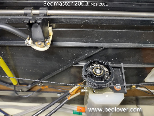
Once completed I only had to wind the cord around the dial components per the service manual and slip the end loops over the hook in the spring part (that attaches to a post in the pulley).

Here are some photos of the restrung dial cord.


You may have noticed in the photos that the display board was removed from its location.
That is the next restoration step I worked on.

The display board has four lamps (Power On, FM Stereo, Tuning Balance 1 and Tuning Balance 2).


I removed the old double-sided foam tape and replaced it with some modern 3M double-sided tape.
Here are the new lamps I received from Martin Olsen installed.


There is a fifth lamp that I need to replace.  That is the one on the dial pointer.
Power to all the lamps pass through the dial pointer lamp so it has to be present (and not open circuit) for any of the lamps to function.

This is where I ran into a problem.
It turns out that the dial point assembly on this Beomaster 2000 had seen better days and someone had tried some repair work sometime in its past.

Here is what it looks like removed.


The worst part is that someone glued and taped the assembly together.
It is impossible to replace the lamp inside without breaking into the glued casing.

That was my only option.

I was able to salvage the pieces in such a way that I have a pretty good chance of rebuilding a dial pointer assembly from them.


Fortunately I checked with Martin Olsen and he just happened to have a spare Beomaster 2000 (Type 2801) dial pointer assembly.  It is now on its way to me for this project.

In order to continue on with testing the Beomaster 2000 I used a spare lamp holder and connected the replacement dial pointer lamp up so the Beomaster could turn on that the other lamps checked out.


The lamps work now :-).  
The one that is not illuminated works when a station is properly tuned in.

However, the fact that it isn't illuminated in the picture here represented another problem I ran into.

I couldn't tune in any FM stations. When I tried I would hear a very short burst of sound from a station but then it would go dead.  Attempting the station tuning with the muting switch disengaged would allow me to hear faint stations (and no stereo) but as soon as I dialed them in better the sound would go dead.

This problem lead me to monitoring the FM mute signal.
Sure enough, the mute signal was active (about 22V) when a station was dialed in.
When I switched sources to Tape the mute signal would drop down to about -8.3V.

The Beomaster 2000 has a source muting circuit to mute the preamplifier audio to the output amplifier whenever a source selection is made. In addition, there is an FM muting control signal that ties into the audio mute whenever a station is being tuned.

Interestingly, the Beomaster 2000 has a switch to turn the FM station muting on and off.
In this case that function was not doing anything. I always had a muted FM audio signal.

Here is the schematic of the Beomaster 2000 FM muting.
Note that I show two versions of the schematic. One is from the service manual.  The other is drawn up per the way this Beomaster 2000 unit is actually wired.


The service manual schematic shows 2R40 as a trimmer resistor for adjusting the FM muting circuit.
That looked like a good place to start on this Beomaster FM problem...until I went to adjust it and it wasn't there.  

The circuit diagram on the right is how the PCB 2 board is on this Beomaster unit.
I am guessing that perhaps this Beomaster unit is an early serial number (and version) while the service manual shows an improved circuit.  I don't know for certain yet but you can see that there is no trimming resistor specifically for FM muting on the Beomaster 2000 of this project.

Related to the FM muting circuit are the FM Detect Balance and the Indicator Balance circuits (also shown in the diagram).

Each of those circuits have a trimmer resistor for adjustments.

When I changed those I started getting some FM station tuning results and some movement on the problem FM muting signal.

Here is what the actual PCB 2 looked like in the area that goes with the schematic above.


Trimmers 2R28 and 2R31 didn't look like they were in too good of shape.
I replaced them and when I measured them by themselves they did have some dead spots.
I decided to check the transistors while I was de-soldering components.
2TR6, 2IC2 and 2IC 3 all measured good (out of circuit) so I put them back.
The tantalums I spot checked earlier measured right on so I hadn't check the three involved here (2C20, 2C51 and 2C52). These three are 0.1uF capacitors.  When I de-soldered and checked them here, they measured around 0.07uF. So 30% out of tolerance. 

I replaced the trimmers (2R28 and 2R31) and the three 0.1uF tantalum capacitors.

Here is the board after those changes.
I have an oscilloscope probe attached to the FM muting signal for monitoring (while I adjust trimmers 2R28 and 2R31).


Here is a closer look at the FM muting circuit components on PCB 2.


With these changes I was able to adjust the FM Detect balance and the FM Indicator balance trimmers so a tuned in station displays evenly on the two tuning balance lamps, the FM stereo light functions correctly and the audio muting circuit behaves properly.

There are still some additional checks that I want to make and when I receive the replacement tuning pointer assembly I will have to install that.

I have a question I need to figure out the answer for on the display lamps.
When I switch from an FM source to Phono or Tape the bottom tuning balance lamp (IL2) displays at full illumination to match the Beomaster 2000 Power On lamp.

I don't know if that is proper behavior or not. It seems like neither FM indicator lamp should be illuminated if a Phono or Tape source button is pressed.  The Tape source is working well and FM stereo stations are being tuned in. I haven't found any adjustment for that indicator lamp other than the balance trimmers...and they are currently adjusted so that FM signals are received on both channels evenly.

I will have to track down the signal that is causing the IL2 balance lamp to illuminate when a Tape or Phono source is selected.

Saturday, October 31, 2020

Beomaster 2400 Type 2902 - Canada Project Indicator Lamps Replaced

 The indicator lamps are now all replaced on this Beomaster 2400.  The old lamps (except for one) were still working but the age of the lamps is unknown so with this restoration it will be documented when they were changed.

The only lamps I converted to LEDs are the three lamps for the Bass, Treble and Balance position indicators.  Those lamps have no function in the circuit except to illuminate the slider positions when the Beomaster is on.  From past Beomaster 1900/2400 projects I like using two LED devices per lamp position here to give the light coverage on the indicator masks.  The reason to change these three incandescent lamps is because the give off the most heat which I have seen cause damage to the indicator masks. You can also see in the photos that the center of the red indicators lenses on these three lamps is faded white due to the heat. The replacement LEDs will run much, much cooler.


The rest of the Beomaster 2400 (and 1900) lamps do directly affect the circuits they are indicators for.
So I will replace those using replacement lamps the Beomaster owner sourced from Martin Olsen.

Here are the Volume Control and Source Select lamp boards with their new lamps.


Now with the lamps all replaced I rechecked the volume muting circuit when a source is selected.


The resulting voltage levels and volume muting duration are pretty much the same as with the old lamps. This is something I can note and use when comparing the next Beomaster 2400 (or 1900) receiver.

I am now ready to recheck the service manual adjustments again before playing some music through this receiver.

Tuesday, December 31, 2019

Beomaster 2400: Indicator Lamp Checks

Now the project gets to the fun part...reassembly and testing.

First thing is to put all of the parts I removed back and turn the Beomaster 2400 on.

I want to see if the replaced lamps all work and I will want to measure the Beomaster power supplies.

This post will show the testing of the new lamps.  The volume level indicator lamp module and the Bass/Treble/Balance module have to be re-soldered in place first. 

Here is the volume level lamp module reinstalled.


...and here is the Bass/Treble/Balance lamp module.


With the Beomaster powered on these two lamp modules illuminate.  


The source and FM tuning indicator module has two connectors so no soldering is required to reinstall it.

The lamps on this module all worked except one, the FM3 source selection lamp.
It turned out that I had the LED replacement lamp installed with reverse polarity.  I switched it around and then it too worked.


I was curious as to how I got the polarity wrong on the FM3 source indicator board. I used the previous Beomaster 2400 restoration project as a reference so the polarity should have been correct.
Looking at the previous project I now see that this indicator lamp panel has differences more than just the two board connectors.

Here is the Beomaster 2400 Type 2902 indicator board from my previous restoration project. The FM3 lamp (between the two board connectors) does not have the jumper that the current Beomaster 2400 does.  The same is true for the Beomaster 1900 Type 2903. The wiring path for that lamp is indeed different...as I found out.


On to the power supply and no-load current adjustments.

Monday, December 30, 2019

Beomaster 2400: Lamp Replacements

This post shows my Beomaster 1900/2400 lamp replacement method.

I replace the two volume level indicator lamps with new incandescent type lamps. These lamps are part of the the volume level circuit and need the lamps to be the incandescent type of lamp.

This is the board with the original lamps.


Here is the board with two new incandescent lamps installed.  I source them from Martin Olsen.


Next is the update to the Beomaster 2400 source selection and FM indicator lamps.
Again, here is the original lamp board for the source selection and FM indicator lamps.
I marked the positive side on the lamps I will be replacing with LED type bulbs.


First is the replacement of the three incandescent bulbs for (FM Stereo indication and FM tuning).


Next are the replacement of the source selection indicator lamps with LED modules.
These are a bunch of my homemade LED assemblies. The single ones are for the Beomaster 1900/2400 source indicator lamps. The dual LED assemblies are for the Bass, Treble and Balance position indicators.


Last are the replacement of the incandescent lamps for the Bass, Treble and Balance indicators.
Here is a picture of the board with the original incandescent lamps.


I always change these lamps to LED type lamps.  I often find that the plastic position indicator masks that fit over these lamps are damaged due to heat from the lamps. The LED replacements operate at a much lower temperature so should be better for the long term and are not damaging to the plastic indicator masks.


In the next post I will reassemble the Beomaster 2400 next and check the results of the restoration work so far.