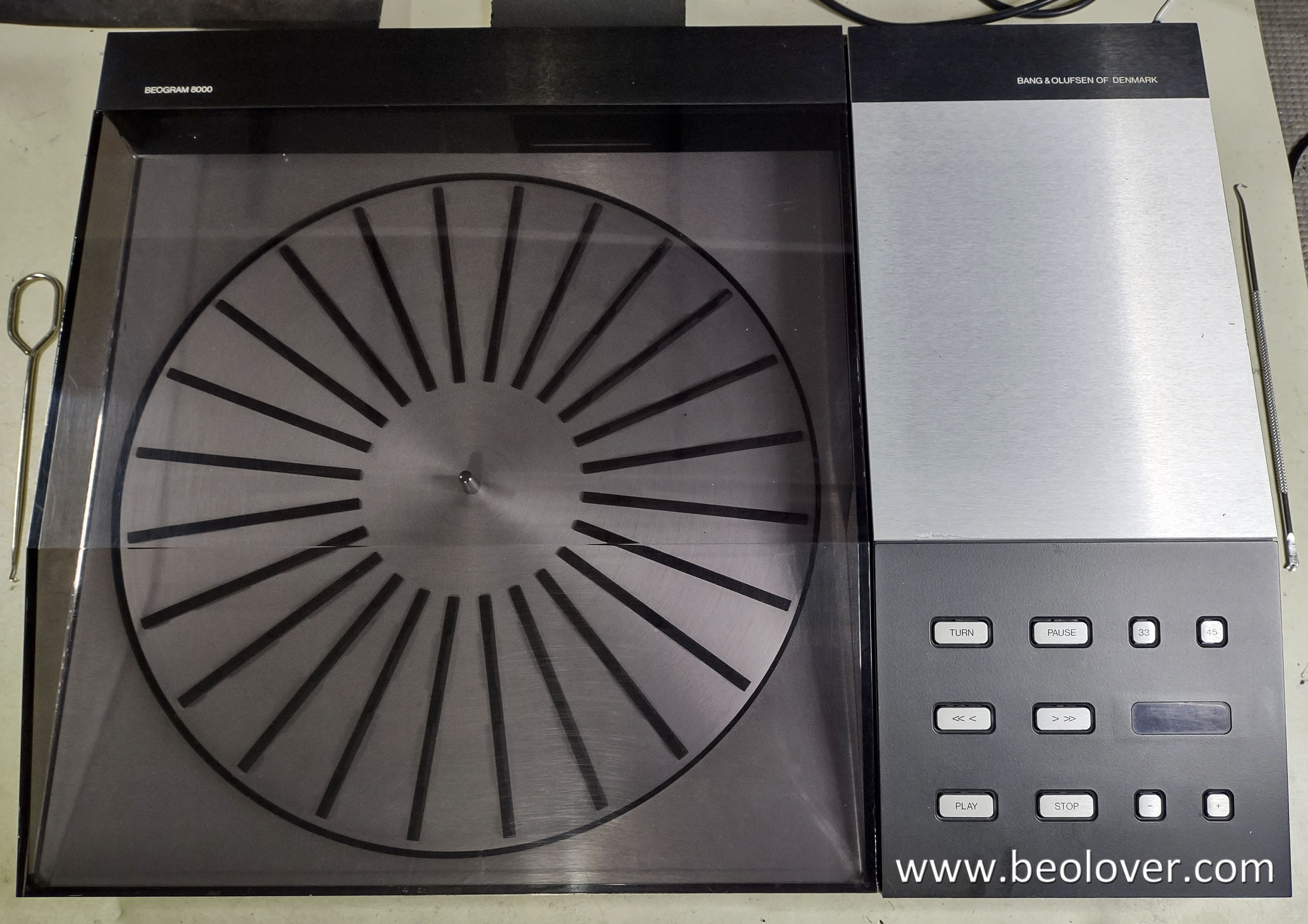
In this post I will go over the various Beogram 8000 restoration tasks that I completed.
As we often do with Bang & Olufsen linear tracking turntables, I started with the floating chassis.
There are only a couple of capacitors to change out on the Beogram 8000 floating chassis but there are quite a few other tasks.
Besides replacing capacitors 0C1 and 0C2, I check the platter hub tachodisc, replace the phono signal muting relay, clean and lubricate the tangential arm assembly, perform some early stage service manual adjustments and replace the servo motor belt.
I will start by showing the removed floating chassis again.
This Beogram 8000 is missing its serial number information but I can tell from the missing factory modifications and the version of the platter speed sensor that this is an early serial number Beogram 8000 unit.
However, it already has its tachodisc upgraded from the original plastic tachodisc to the B&O metal disc.
The phono audio muting relay (in the DIN plug housing) is the National type so I replaced it with the Beolover replacement relay component.
As I mentioned above, this is an early serial number model and the 0C1 capacitor for the +5 V regulator is not the 1 uF value that later Beogram 8000 units had installed. I upgraded 0C1 to 1 uF. I also swapped out 0C2 with a new 47uF, 10 V electrolytic capacitor.
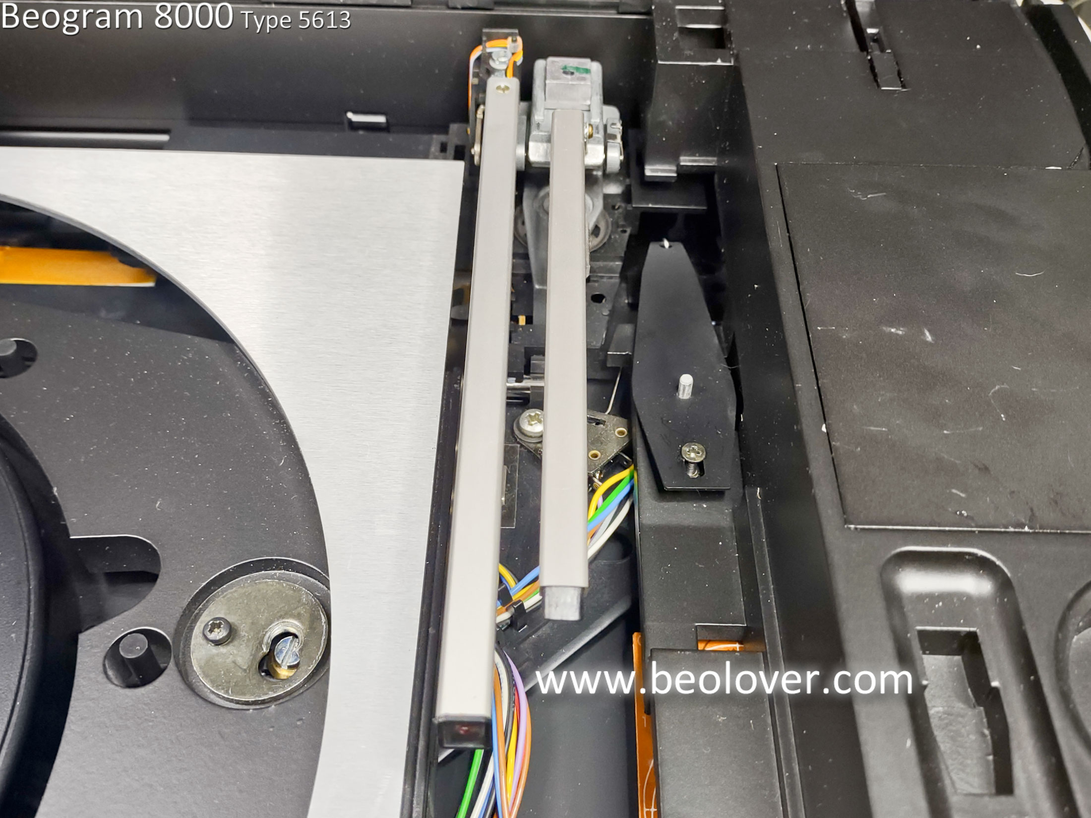
Next, I partially disassembled the tangential arm assembly for cleaning, inspection and lubricating.
Inspecting the underside of the tonearm assembly I examined the arm lowering components for dirt and any obstructions.
The Beogram 8000 tonearm lowering operation can sometimes drop the arm suddenly from the raised position to a record. The causes of those faults can be due to metal on metal contact between the back (underneath part) of the tonearm and the tonearm height adjustment screw. Over time the arm wants to stick to the screw instead of lowering. When the arm lowering lever moves to control the slow descent of the arm to the record, the tonearm stays behind (seeming stuck in the raised position). The weight of the arm finally overcomes the problem and the arm drops...but without any control over the lowering.
This type of problem can be corrected by placing a thin piece of non-conductive material between the back of the tonearm and the tonearm height adjustment screw. I like to use a small piece of
Dura-Lar (made by Grafix).
I used a little bit of epoxy to keep the Dura-Lar in place.
Because the bottom of the Beogram 8000 tonearm is easily accessible during this stage of the restoration I like to perform the adjustment for the height of the fixed arm from the surface of the platter and the alignment of the tonearm to the fixed arm.
Tonearm adjustments for a lot of turntables is a very involved process. Bang & Olufsen has always strived to make that relatively painless. Granted, part of what makes a Beogram easier to adjust is the fact that the phono cartridge is integrated into the tonearm.
On the Beogram 400x turntables the platter height is adjustable and the service manual specifies a required distance of 23 mm from the platter surface to the top of the fixed arm (and tonearm).
In that adjustment the platter is actually raised and lowered to achieve that distance.
The 23 mm is the B&O calculated height to achieve a vertical tracking angle (VTA) for proper record play by the B&O MMC cartridge.
On the Beogram 8000 the service manual also specifies a distance of 23 mm from the platter surface to the top of the fixed arm (and tonearm). However, there is no adjustment of the Beogram 8000 platter assembly to alter that distance. A small screw on the fixed arm can adjust the position of the end of the fixed arm (to the platter) but the mounted position of the fixed arm and the tonearm (at the pivot point of the tonearm) is not adjustable. So the vertical tracking angle (VTA) on the Beogram 8000 is built into the tonearm design and the tonearm pivot point is fixed for the correct VTA.
The adjustment of 23 mm for the end of the fixed arm to the platter surface and the corresponding alignment of the tonearm to the fixed arm (the horizontal parallelism) are for cosmetic purposes.
I suppose the 23 mm distance at the end of the arm also ensures that the stylus does not hang too low when it is scanning a record.
The screw on the fixed arm and on the underneath side of the tonearm are for adjusting the ends of the arms from the platter surface...not the height of the tonearm at the arm pivot point and not the vertical tracking angle.
It is important to perform this adjustment per the service manual though, as the goal of the restoration is a properly functioning and proper looking Beogram 8000.
To perform this adjustment I install the Beogram 8000 tangential arm assembly on the two guide rails but leave the position spindle off. That allows me to manually slide the tangential arm assembly over the platter without having the Beogram 8000 fully assembled and working.
Once the end of the fixed arm is at a height of 23 mm from the platter surface, the tonearm height adjustment screw can be used to align it (the horizontal parallelism) with the fixed arm.
The Beogram 8000 floating chassis can now be reassembled with a new servo motor belt and I can move on to the electronic restoration tasks.
I will leave the tracking force adjustment and record tracking sensor adjustment until I have the electronics portion of the restoration complete.
For the electronic restoration I started with the Beogram 8000 processor assembly, PCB 2.
That is the circuit board inside the metal shield box that attaches to the main board.
There is only one electrolytic capacitor on PCB 2. That is 2C28 which is a filter capacitor for the +5 V power to the board.
In this Beogram 8000 PCB 2 the 2C28 is easy to get to. There is normally another small add-on board (8005065) covering it.
That brought up a decision that I had to make about this restoration.
Because this is an early serial number Beogram 8000 it sends the speed sensor signal directly from the operational amplifier (op-amp) on the main board (PCB 1) to the processor (uC) on PCB 2.
Later serial number Beogram 8000 units and all Beogram 8002 units have a small add-on board containing a flip-flop circuit that the speed sensor signal is sent to first...before going on to the uC.
The flip-flop is clocked by the same clock as the uC and makes the speed sensor signal a cleaner rectangular waveform. B&O added this flip-flop circuit to fix periodic variations of turntable speed.
Here is the B&O modification description from a later Beogram 8000 service manual.
I decided that this modification really should be applied to this early serial number Beogram 8000.
Note: In fact, I returned to my previous Beogram 8000 project from Houston and installed it there as well.
I removed the uC IC from PCB 2 first, along with the 40-pin IC socket.
I always do that anyway on a Beogram 800x restoration because I like to install a new 40-pin socket.
With the 2C28 capacitor and the big uC IC and socket out of the way I have a lot more room to install the speed sensor signal modification per the service manual.
I also measured the old 2C28 capacitor. The 47uF value was just barely out of tolerance.
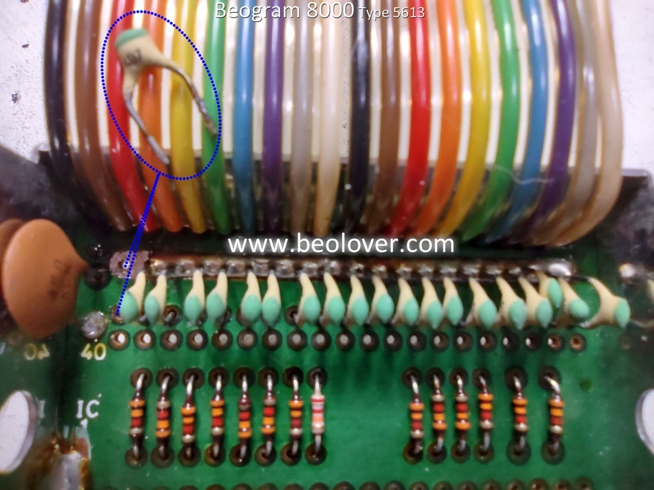
For my implementation of the speed sensor signal modification I started by removing the 4.7nF ceramic capacitor 2C25.
Then I cut the copper foil trace between connector P6-2 and the uC IC (2IC1) pin 40.
Now the speed sensor signal from P6-2 will be re-routed to the add-on board as the input to the flip-flop (2IC3 pin 5). In keeping with the suggested color code I will use a yellow wire for that connection.
First, I have to de-solder hole "C" in PCB 2 and expand its diameter a bit with a hand drill.
Then I could install a yellow colored wire from P6-2 through the hole "C" for routing to the add-on board.
I prepared the wires for the add-on, speed sensor signal conditioning board.
Per the service manual instructions, the blue wire is for ground, the red wire is for +5 V, the green wire is for the clock and the orange wire will deliver the speed sensor signal back to the uC (2IC1) pin 40.
Here is PCB 2 with the new add-on board, a new 2C28 capacitor and a new 40-pin socket (for 2IC1) installed.
...and here is 2IC1 installed in the new socket.
PCB 2 is ready to go so I continued on with the board restoration of PCB 1 (the main board ... that hosts PCB 2).
Here is the before photo of PCB 1 by itself.
Here is PCB 1 with all of the small electrolytic capacitors replaced. Only the three larger ones remain to be added. While the board was in this stage I turn it over and re-flow the solder on all of the board connector pins. It is well known that those connections can develop hairline cracks. It is also a good time to inspect all of the traces for any breaks.
As I like to do, I removed the ground mounting ring from the original 1C27 (2200uF, 40V) capacitor and reuse it on the replacement 1C27 capacitor.
That completes the PCB 1 restoration work.
Next up is changing capacitor 4C1 inside the Beogram 8000 transformer assembly.
4C1 is a bipolar capacitor for the Beogram 8000 platter drive motor.
Its value varies depending on the line voltage where the Beogram is used.
The Beogram 8000 is fitted with a fixed transformer for the country's voltage it is made for.
For example, Europe's line voltage is at 50 Hz while the voltage in the North America is 60 Hz.
The value of 4C1 for a 50 Hz line voltage is 39uF but for a 60 Hz line voltage it is 27uF.
Since this Beogram 8000 is North American model I replaced 4C1 with a 27uF capacitor.
I haven't found a good non-polarized capacitor for that value so I put two 56uF capacitors in series (with their negative leads connected together). This results in an acceptable 28uF.

The last step of the electronic restoration tasks is to add a test connector to the forward and reverse scanning sensor buttons in the control panel. I like to be able to check and adjust the sensitivity on the scanning sensors without having to open the Beogram 8000 back up. Adding a little three pin test connector lets me connect a multi-meter for testing by just opening up the control panel plate.
All of the initial restoration steps are now complete and I can assembly the floating chassis components with the electronic components for a quick test.
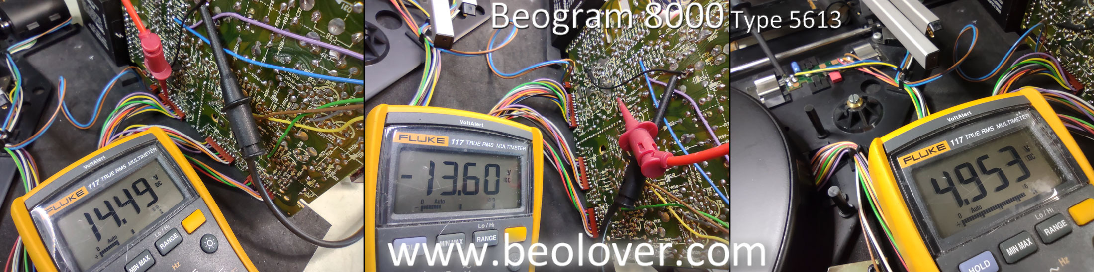
I haven't set the record tracking and tracking force so I won't try actually playing a record yet...but I can test the platter speed detection, record detection and scanning functions.
Those are the results I wanted to see. Everything looks great so far.
In the next post I will check power supply voltages, adjust the scanning sensitivity, tracking sensitivity and tracking force. After that I can test play the first record.