After opening up the receiver I started the capacitor replacement on the main board, PCB 5 (AF Amplifier, Power Supply, Muting and Silent Tuning). Like the low profile Beomaster 1900 and 2400 receivers the Beomaster 4400 is not very easy to work on. The main board has a lot of capacitors to replace and there is no "service position" like the Beomaster 6000 (Type 225x) and 8000 (Type 190x) where individual boards are relatively easy to remove and replace. Bang & Olufsen did design the Beomaster 4400 where four small boards do completely disconnect via connectors. Those are PCB 1 (Front End), PCB 2 (IF Section), PCB 3 (Stereo Decoder and Indicator Circuit) and PCB 4 (Pre-Amplifier). So at least that is something :-).
Here is the PCB 5 board before the recapping work. You can also see the component side of the board has some dust on it. I will clean that as I go.


I took the disassembly one step further and removed the TIP 141 (NPN Darlington pair) and TIP 146 (PNP Darlington pair) components from the big heatsinks. I will be changing the thermal coupling of those components anyway and removing them from the heatsink now frees up the PCB 5 board to flip over as I de-solder and re-solder capacitors.
Here is the PCB 5 after replacing the capacitors. I also replaced trimmer resistors 5R177 and 5R277 which will be used for the no-load current adjustment later.


Here are the two new 10,000uF reservoir capacitors (for the ±35V rails) flipped around to show their connections.


Here is PCB 5 with the reservoir capacitors turned back around and in their holding bracket.
Thirty-four capacitors replaced counting the two ±35V reservoir capacitors.

Now on to the PCB 4 (Pre-Amplifier) board.
Here is the board before the recap.

Here is the recapped board. Most of the values were 1.0uF and 2.2uF so I replaced them with WIMA polyester, non-polar capacitors (MKS). A total of seventeen capacitors replaced on this board.

I replaced the tantalum capacitors with WIMA capacitors as well. Some restorers will prefer to keep tantalums or replace them with new tantalums. I don't have a problem with that. Tantalums are an expensive capacitor so the B&O designers chose them for a reason. However I prefer using the WIMA MKS capacitors. They have performed well for me so far. Perhaps I will restore my own personal Beomaster 4400 going the tantalum route. It would be interesting to compare. I will add that on this Beomaster 4400 the existing tantalum capacitors still measured in spec regarding their capacitance value.
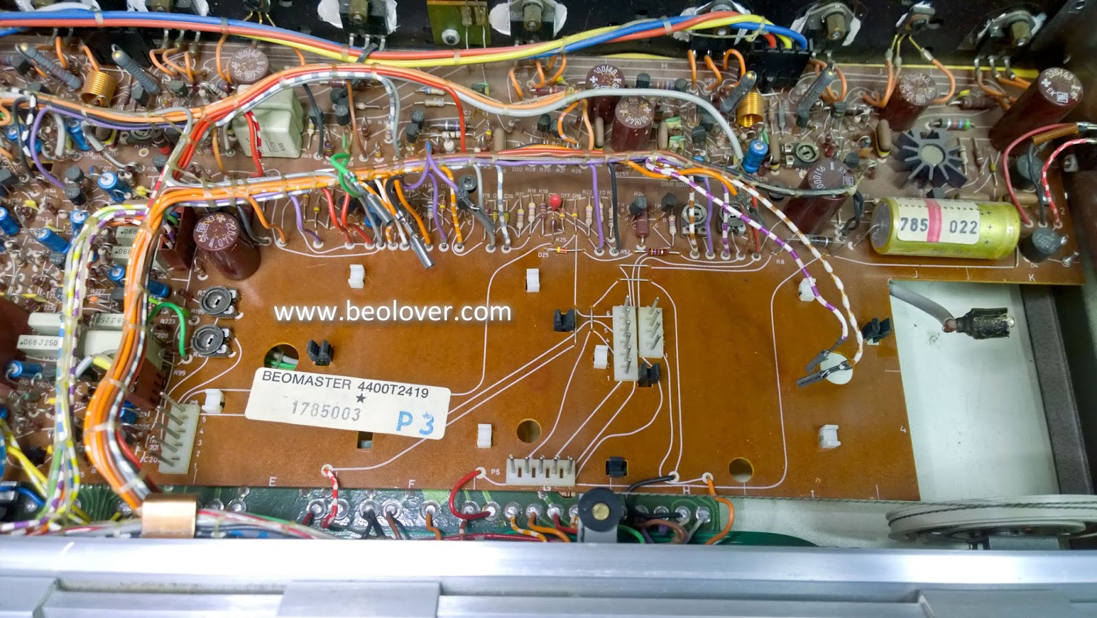
Now for PCB 3, the Stereo Decoder and Indicator Circuit board.
Here is the before picture.

I used the same replacement capacitor strategy on this board as I did on the pre-amplifier board.
WIMA MKS capacitors where possible and electrolytic capacitors for values over 4.7uF.
Ten capacitors on this board.

The final two boards are PCB 1 (Front End, inside the metal box) and PCB 2 (IF Section).
Here is the before photo.

PCB 1 (Front End) has one 10uF tantalum capacitor inside the metal box. It measured in spec and I decided to make an exception and keep that capacitor on the board for now.
On PCB 2 there is a 1uF and a 4.7uF electrolytic capacitor and I replaced those with WIMA MKS types.

The capacitor recap work is done and I am ready to reassemble this Beomaster 4400 unit. Time to see if it comes to life now.
No comments:
Post a Comment
Comments and suggestions are welcome!