Featured Post

Beolover SyncDrive: DC Platter Motor Replacement for Beogram 4002 and 4004 (Type 551x and 552x)

Late Beogram 4002 and the 4004 (Types 551x and 552x), which have DC platter motors instead of the earlier synchronous AC motors usually suff...

Showing posts with label 66LLBM8000. Show all posts

Monday, March 14, 2016

Beomaster 8000: Installation of New Keypad Ribbon Cables

I recently received the lower front panel of a Beomaster 8000 for the installation of new keypad ribbon cables. The original ones had developed some bad contacts in the attached headers.
I designed proper replacements and had them custom manufactured:
I extracted the original ribbon cables and installed the new ones:
Then I open up one of my Beomaster 8000s and tested the keypad with the new cables:
Beolovely!! All keys worked as they should and so hopefully this restoration will come to a successful end soon!


Saturday, October 31, 2015

Beomaster 8000: Repair of a Ripped Off Keypad Ribbon Cable

I recently repaired a ripped off ribbon cable in a Beomaster 8000 that connects the volume rotary encoder to the microcontroller board. I thought I was done, but the front panel came back, now with the frequency encoder cable broken off. The hot glue that I used to fix it in place had come off from the cable, and subsequently it broke off during the rigors my customer's restoration effort put on the solder points:

At least this time I was able to reuse the cable in its full length, so I could simply remove a bit more insulation and solder it back in. I removed the keypad PCB, cleaned the solder points and then did the soldering:
Then I glued it on with epoxy to the PCB back, hoping this will be more durable:

After that I reattached the PCB using new (they should not be reused after taking them out) 3mm retaining clips and nylon washers to protect the PCB. Then it was time for testing. I put the panel into the Beomaster 8000 that I am currently restoring for another customer and turned it on. I tested all keypad buttons and both encoders, and everything seemed to work properly. I hope this was the last time I worked on this particular panel and this 8000 will finally be happy!

Friday, September 4, 2015

Beomaster 8000: Test of Repaired Front Panel Ribbon Cables

After reattaching the severed ribbon cable of the Beomaster 8000 front panel and cleaning the contact pads of the program and source keys, I tested the panel in one of my own Beomasters. It worked nicely, all buttons responding precisely and the rotary encoders doing their job. Here a couple of impressions:


Time to send this panel back that it can continue serving in its own Beomaster!

Beomaster 8000: Repair of a Broken Off Keypad Ribbon Cable

I am assisting a Beomaster 8000 restoration. Today I received the front panel of this unit with an almost completely severed keypad ribbon cable. These ribbon cables easily break off if the Beomaster is opened a few times. Often the glue that fixes the cables to the keypad PCB fails at this age and the 24 gauge leads take the brunt of the cable flex every time the panel is lifted. They only survive this a few times and then they break off. If only one or two break off, this can be fixed by inserting a bit of copper braid and with some flux and solder the connection can usually be restored. However, in this case most of the leads were broken off:


So it was time for some microsurgery. I removed the PCB. This required to cut the original retaining clips, which are of the non-removable type. They can easily be replaced with 3mm retaining clips, so this is not an issue. There is an earlier blog entry that details this procedure.

Once the board was removed, I cleaned up the solder points and then prepared the cable. I had to extend the length a bit since I needed some 'meat' to rebuild the connections. If the cable is too short it is difficult to put the panel into service position with connected ribbon cables. I made eight extensions from an old computer ribbon cable:


Then I soldered them to the prepped ribbon cable leads:

A bit of shrink tubing of the proper color finished the job:

Then it was time to solder the ribbon cable back in:


I also embellished the leads of the other ribbon cable with some solder to stabilize them. They were still intact, but I could see that they also had started breaking off.

Since I was in there, I decided to also clean the contacts of the keypad switches. They usually are a bit oxidized. The oxide layer can easily be removed with a fiberglass pen. This shows the P7 switch before cleaning:


And after:

I did the same with the contact springs. this pic shows one before. The dark spot is the oxide.


Unfortunately, I forgot to take a picture of the cleaned spring pad. They also get nice and shiny after the fiberglass pen treatment.

Then I put the PCB back in using 3mm retaining clips and #4 nylon washers to protect the PCB:


Then it was time to glue both of the ribbon cables to the PCB to protect the cable leads from further bending events. I used hot glue (like the original setup):


That should do it! 


Thursday, April 16, 2015

Beomaster 8000: uProcessor Board - Jumpers/Resoldering Vias and Two New Capacitors

The Beomaster 8000 display board that I just restored came with the uProcessor PCB attached. So I checked on the B&O recommended jumpers that bridge the bunch of vias that often go intermittent on these boards. Here is the view from the top after removing the EMI cans:

And from the bottom. It appears that the jumpers were put into place already during an earlier visit to a service department:

I reflowed the vias that they did not cover, and then replaced the two electrolytic capacitors on the board:

After this I replaced the can covers and then cleaned all headers with a fiber glass pen. A thin DeoxIT D100L coat on the header pins finished the job.


Beomaster 8000: Replacing the Incandescent Indicator Light Bulbs with SMD LEDs

It was decided to also replace the incandescent indicator light bulbs of the Beomaster 8000 display board that I recently received for rebuilding. I think that was a great idea, since these light bulbs are notorious for breaking during shipping - they often have brittle leads that break off right at the point where they enter the glass bulbs.

For some time I wondered how to improve the process that I developed last year. So far, I replaced the bulbs in all my 8000 restorations with two through hole-style LEDs in series with a resistor. While this worked great, I thought this could be improved by the design of small circuit boards that hold three surface mount LEDs with their resistors. So I took this opportunity to go for it! I made a short video about the process (in a sense this is an update to my earlier video):


Here are a few pictures:

The assembled PCBs. Every PCB has three LEDs in parallel:

Installed in comparison with an original light bulb (the bulb is a bit too red tinged - I think the camera was confused by the LEDs...):

With red covers on. The LEDs yield a very similar appearance as the original light bulbs:

This picture shows the appearance after replacing all four bulbs:

After this was done I also replaced the two electrolytic capacitors on this board to complete the job. Now everything is beolovely in display-land! Time to ship this board back to its Beomaster 8000!

Sunday, April 5, 2015

Beomaster 8000: Display Repair (II) - Reassembly and Final Test

This is the second part of a Beomaster 8000 display restoration post. The 24hrs test of the installed SMD LEDs passed uneventfully. So I put the displays back together. I used the 'glue gun method' I developed recently to secure the display covers back in place. I really like this method, since it seems to make a strong lasting bond, while still leaving a way to cleanly opening the displays up again should there ever be a problem again down the road. I usually try to stay away from the use of glue etc...due to the often irreversible character of the outcomes. But in this case there are not many options. But the unique properties of the polyurethane glues used in glue guns makes a clean reversal possible. My tests showed that the glue can be fully removed without leaving residues if necessary.

After putting them back together I tested them again in my fixture:

Seems all went well! So I installed them back on the PCB:

Here a detail shot of the input display. One of the two glue strips is visible on the side:

I installed the board again in my Beomaster 8000 and applied my standard intensity adjustment procedure:

Another Beomaster 8000 display restored to full glory! This is Beolove!


Saturday, April 4, 2015

Beomaster 8000: Display Repair (I) - Installation of SMD LEDs and Test

Last week I was sent a Beomaster 8000 display board for rebuilding the displays with surface mount LEDs. I installed the display into one of my Beomasters and had a look:

Many segments were dead. A clear case for a rebuild. As usual the balance display was still good. So far I have to find a broken balance display yet. Their boards look differently, i.e. they seem to have come from a different manufacturer. I set out to rebuild the display with SMD LEDs. Here are a few pictures of the process. Display board removed:
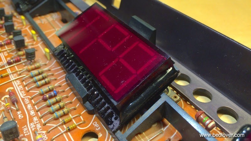
Displays liberated. It is best to take the top three out at once. Otherwise it is easy to damage the plastic alignment fixture:
Removed from the plastic fixture:
Opened up:
This shows the frequency display board after removing the original LEDs:
SMD LEDs lined up for population of the board:
After installing all LEDs. Now I will run them for 24hrs in my test fixture to make sure everything is stable: