I was asked to complete the exchange of the electrolytic capacitors in the Beogram 8000 that I am rebuilding right now. So I extracted the PCBs and went about it:

In order to get the PCBs out it is best to take the PCBs off in one block from its 'hooks', then pull out the ribbon cable that comes from the control / display panel and then take this panel also out to extract the RPM display which is connected to the uProcessor can via a ribbon cable. Here is a peek into the control panel 'cavity' after taking it out (with the PCBs in place):

About half of the capacitors were already replaced. I cleaned up a few splashy solder points and then extracted the uProcessor can from the main PCB. then I opened it up:
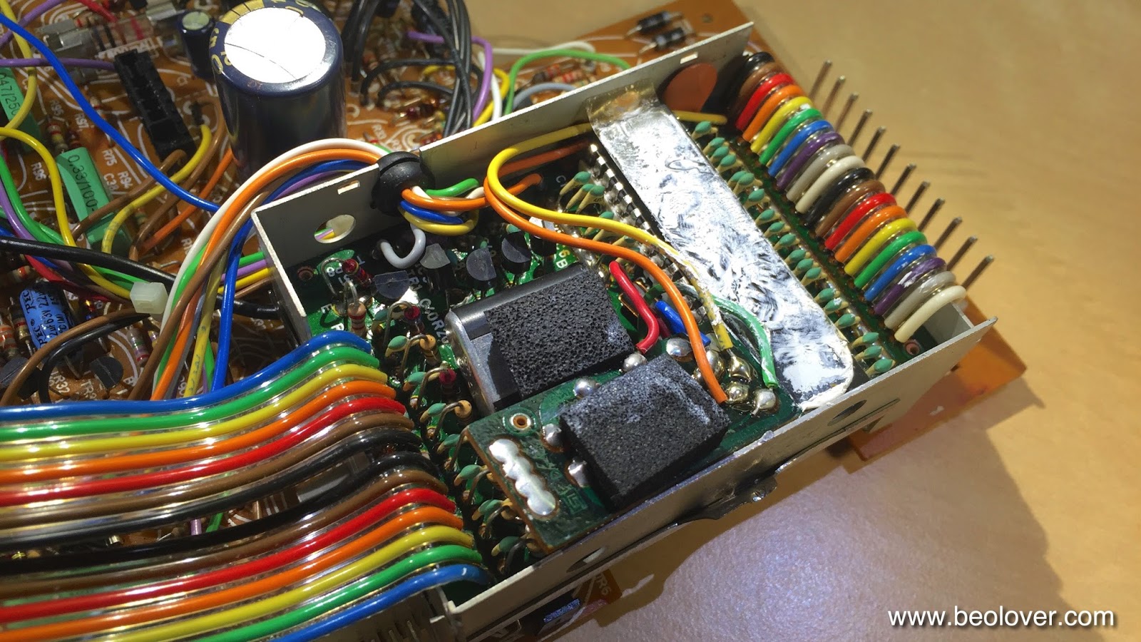
The later added HEF4013 flipflop board is installed (the small PCB towards the front with a piece of foam on top). Apparently the output of the speed sensor amplifier was not clean enough to give a stable signal to the uProcessor and so they put this flipflop in-between (see sec. 8-4 in the Beogram 8000 Service Manual). Underneath this board the decoupling capacitor of the uProcessor is found. This picture shows the new one that I installed:

After this I buttoned the EMI can up and replaced the capacitor that sits underneath the can before mounting it again on the main PCB:

Here is a picture of the new one:

After that I went on to the 'Settling Circuit' and 'Control for uC' boards that are attached to the main board with one single screw:

After replacing the caps on them I cleaned up their mounting with a second M3 nut that gives the Settling Circuit a bit more space and takes some flex-stress out of the equation and put some decent insulation under the Settling Circuit board with Gorilla tape

which resulted in a straightened up arrangement.

A bit strange this entire design in my opinion...It almost appears that they designed it in several installments and kept adding circuits.
After replacing a few more easily accessible caps on the main board I finally put everything back together and then replaced the 47uF capacitor on the 5V regulator that is mounted to the bottom pan for heat dissipation:

This shows the new one:


