Featured Post

Beolover SyncDrive: DC Platter Motor Replacement for Beogram 4002 and 4004 (Type 551x and 552x)

Late Beogram 4002 and the 4004 (Types 551x and 552x), which have DC platter motors instead of the earlier synchronous AC motors usually suff...

Showing posts with label control panel. Show all posts

Saturday, January 5, 2019

Beogram 8000 Type 5613: Finishing the floating chassis components, transformer C1 replacement & cleaning the control panel

Last night I wrapped up the work on the floating chassis components.
The cleaned tangential drive components (spindle, spindle nut, rails and new bracket) were reassembled and fitted to the floating chassis.

The spindle was lubricated per the service manual. The specified lubricants are pretty similar to the Beogram 400x. That makes sense as both series of turntables have similar tangential drive mechanics.
One interesting thing on the Beogram 8000 lubrication chart I hadn't really noticed before was the entry for the lid damping grease. It calls out a product called Kilopoise. I discovered it is made by Rocol (Rocol Kilopoise 0868). I found one seller on Ebay that sells it in small samples. Most sellers offer it in a large quantity which costs quite a lot. On these 80's series of Bang & Olufsen components that used various damping controls I have been using Nyogel 767A. It isn't cheap either. So it will be interesting to compare the Nyogel to the Kilopoise.

Here is the lubrication chart from the service manual with some notations I added.


For the spindle components I have the Molykote DX, white paste and I have a very close Rocol grease (MTS 2000 instead of MTS 1000). I also have the Esso NUTO H32. Another interesting thing about this chart compared to the Beogram 400x is this chart doesn't mention coating the rails with a thin layer of the Molykote. I have found that to still be necessary on the Beogram 800x units I have restored.

Here is the tangential arm carriage as I reassembled it.
The spindle has a thin coating of the MTS 2000 and NUTO H32 mixture. The spindle bearing and rails have the Molykote DX grease.

I should also mention that there are other modern lubricants that are suitable for this and I have used other types before. My reason for finding and using the original specified lubricant products is solely out of curiosity.


The floating chassis is ready for use.

Before getting to the task of restoring the main board and the microcomputer board I decided to knock out a couple of smaller tasks.

First the replacement of the C1 capacitor for the platter drive that is located in the transformer box.
Beolover makes a nice replacement for it that fits better than the original capacitor did.

Here is the original one.


Here is the replacement. If only all of the restoration tasks were this easy.


The next item on the list is to check out the Beogram 8000 control panel. It typically needs some cleaning and I like to add a permanently wired test connector for adjusting the forward/reverse scanning LDRs.

When I looked at the back of the control panel to open it up it didn't look too bad...but once I removed the button board I found a lot of dirt. The backside of the button board often has dust but this is a little excessive for a Beogram 800x.


The top plate and the plastic buttons were cleaned up with soapy, warm water. The rest had to be wiped with a mild cleaner and some Kimtech wipes.


Once the button board was cleaned I attached the LDR test connector. The reason I have been installing these is because I kept having cases where the LDR adjustments needed to be repeated after the Beogram 800x turntables were reassembled. It is really difficult to attach measurement probes and do the adjustment when just the control panel is lifted. There isn't much room to do what is needed. The test connector allows me to easily attach a multimeter and still have access to the adjustment screws for the LDRs.


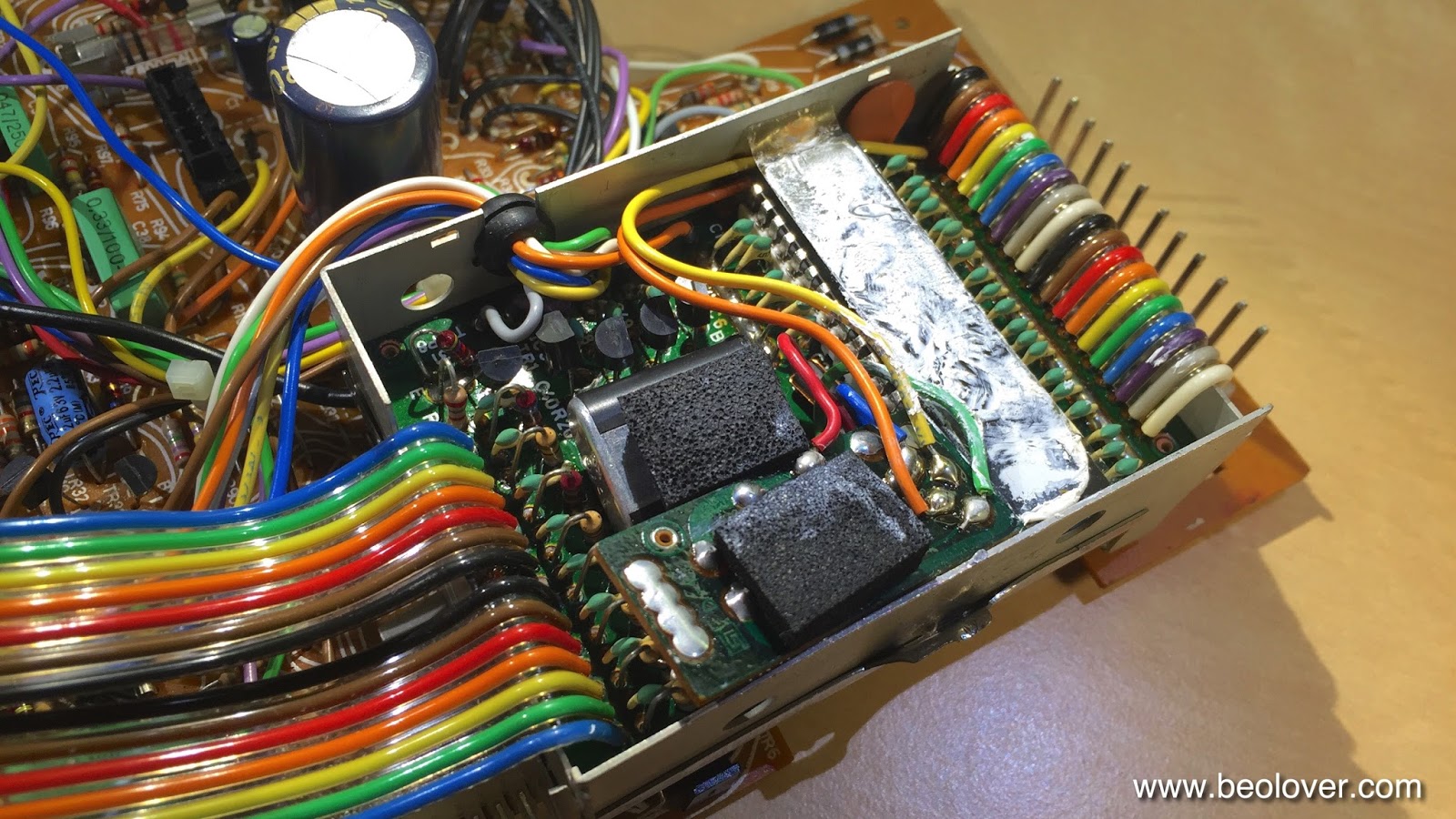
The colors of the wires I use match the color of those corresponding signals in the ribbon cable connecting the button board to the main board. That is the Beogram 800x units that have a color coded ribbon cable. Some units, including this one, have an all gray colored cable. Nevertheless I make the test connector the same on each Beogram. The adjustment procedure calls for measurements between each LDR signal and the ground wire.

Here is the reworked control panel ready for use.


Next up will be the main board and microcomputer board restoration work.


Wednesday, November 21, 2018

Texas Beomaster 8000: Restoration task on the control panel

The Beomaster 8000 from Texas has been playing music beautifully while I have been working the restoration tasks for the Canada Beomaster 8000 unit. However, a couple of issues popped up during the functional testing.

The first problem happened when moving the microcomputer board and display board out of the service position. All of a sudden the Beomaster wouldn't switch on the +15V power supply again. I have gone over the solder joints of the microcomputer board a number of times now and here it goes off again. Quite disappointing.

To confirm the problem is still with this original microcomputer board I substituted one of my spares again. Just like that the Beomaster was working again. Due to this flaky behaviour I am not ready to trust this microcomputer board in completing this project. I feel like this board needs to be stripped completely down and all of the traces (and vias) reworked from scratch.

For this project I am going to go with one of my spare microcomputer boards. It hasn't failed me yet so it will be perfect for this project.

The second problem happened at the same time and was the volume control wheel ceased to work. The Beomaster volume worked just fine via the remote control so the problem had to be in the control panel. Either the wheel sensors or the cables.

The cables are the most likely suspects as this Beomaster has gone through some rough cable repairs in the past.


On these Beomaster 8000 control panels the two ribbon cables and the (blue) wires for the rotary wheel sensors can work loose in their small solder joints.

I had to resolder the connections but I decided to go ahead and replace the two ribbon cables with new replacement cables I get from Beolover. That is the best option for success here.

Interestingly, I hadn't noticed this before, the control panel utilizes a flat, metal spring to hold the panel secure in the center. That spring is the same as the flat springs that are used on the Beomaster press bar that opens the Filter & Tone Controls. Perhaps a substitute can be used here and this spring would be free to replace one of the missing press bar springs.


Here is the control panel button board removed and the installation of the new ribbon cables.


Instead of re-assembling the control panel in its final, permanent configuration I will just tape it in place temporarily so I can test that the control panel works and the volume control problem is gone.

Success, both the volume wheel and the FM tuning wheel function properly now.


Tomorrow I will start putting these components back into their permanent positions in the Beomaster cabinet.

Thursday, November 12, 2015

Beogram 8000: Replacing the Electrolytic Capacitors

I was asked to complete the exchange of the electrolytic capacitors in the Beogram 8000 that I am rebuilding right now. So I extracted the PCBs and went about it:
In order to get the PCBs out it is best to take the PCBs off in one block from its 'hooks', then pull out the ribbon cable that comes from the control / display panel and then take this panel also out to extract the RPM display which is connected to the uProcessor can via a ribbon cable. Here is a peek into the control panel 'cavity' after taking it out (with the PCBs in place):
About half of the capacitors were already replaced. I cleaned up a few splashy solder points and then extracted the uProcessor can from the main PCB. then I opened it up:
The later added HEF4013 flipflop board is installed (the small PCB towards the front with a piece of foam on top). Apparently the output of the speed sensor amplifier was not clean enough to give a stable signal to the uProcessor and so they put this flipflop in-between (see sec. 8-4 in the Beogram 8000 Service Manual). Underneath this board the decoupling capacitor of the uProcessor is found. This picture shows the new one that I installed:
After this I buttoned the EMI can up and replaced the capacitor that sits underneath the can before mounting it again on the main PCB:

Here is a picture of the new one:
After that I went on to the 'Settling Circuit' and 'Control for uC' boards that are attached to the main board with one single screw:
After replacing the caps on them I cleaned up their mounting with a second M3 nut that gives the Settling Circuit a bit more space and takes some flex-stress out of the equation and put some decent insulation under the Settling Circuit board with Gorilla tape
which resulted in a straightened up arrangement.

A bit strange this entire design in my opinion...It almost appears that they designed it in several installments and kept adding circuits.

After replacing a few more easily accessible caps on the main board I finally put everything back together and then replaced the 47uF capacitor on the 5V regulator that is mounted to the bottom pan for heat dissipation:

This shows the new one:


Wednesday, September 2, 2015

Beogram 4000: Replacement of Incandescent Light Bulbs in Control Panel with LEDs

The Beogram 4000 that I am restoring right now had three broken incandescent light bulbs in the control panel. There are four bulbs, two for the position indicator and one each to illuminate the RPM trimmers. When I initially turned this deck on, no light came from any of the bulbs. Nonetheless, one of the position indicator bulbs was still o.k., but since the two bulbs that illuminate this indicator are in series, this did not help. At any rate, this is a perfect demonstration how fragile these bulbs are at this age, and that a replacement of them with LEDs is a great way to enhance longevity and reliability, and to make sure the unit survives shipping.

I recently developed dedicated SMD LED based replacement units that drop in for the position indicator bulbs. I assembled two and replaced the bulbs with them. I also replaced the RPM trimmer bulbs with high intensity red through hole LEDs fitted with appropriate 3.3k current limiting resistors. This brought them down to the proper intensity, making for a gentle but clearly visible low power illumination of the trimmer slots. 

Here are some pictures of the process. This picture shows the original light bulbs in place:


This picture shows the SMD LED PCBs that I used to replace the two position indictor bulbs:

and here after installing them and putting in the two red LEDs to replace the trimmer illumination bulbs:

After I was done with this I tested the functions of the keypad, and I had to realize that the deck does not switch to 45 RPM. Pressing the key did turn on the 45 RPM trimmer illumination, but the motor stayed at 33 RPM. This meant that the control system worked fine, but that there was an issue at the executive end of things. I traced the signal and found out that the relay that is responsible for changing the resonance frequency of the drive oscillator seems to have given up its ghost. It will be interesting to find a replacement.


Thursday, May 7, 2015

Beomaster 8000: Repair of a Broken Out Control Panel Lid Spring

The last Beomaster 8000 that I renovated came back to my bench after suffering shipping damage on the way home to its owner. There were some broken traces on the uProcessor board and a broken out button PCB in the control panel). After I fixed these issues and put it back together, I set out to write a proud email to the owner announcing the swift return of this Beomaster, this time double boxed. A few seconds after I hit the 'send' button, a loud crack happened and a piece of plastic ricocheted past my head. This is what I found. One of these pieces was located on the other side of my work shop:

First I did not quite understand what happened, but then I realized this part must have originated from the Beomaster that sat on the bench next to me! I looked around and found this situation on the back of the control panel lid:
The spring that opens the control panel had broken out of its plastic retainer and the lid hung limp on its hinges. No more springy opening after pressing the bar. This spring is surprisingly strong, and while the lid is closed it stores the energy needed to open the panel. This energy released creating a projectile.

First I asked around if anyone had a decent condition lid (3D printing still has 'finish issues; it is difficult to produce good lucking parts for exterior repairs), but I came up empty. So I further examined the situation and came up with a low impact strategy to fix it. Dillen of Beoworld.org advised me that the plastic bar that holds the spring mechanism can be slid out to the side of the lid. I opened the Beomaster up again and extracted the lid. Then, indeed, the part easily came out from its groove revealing that it is hollow. This opened up a route to a 3D printed fix. Here is a picture of the part that I had printed on a Stratasys uPrint printer in ABS:
I only had access to white filament, so I had to paint the part black on the visible areas. This part fits precisely into the gap in the plastic part and over the spring:

Fully inserted:

Then it was time to test the part under stress. I slid the bar back into the lid:


Then I put everything back together. Here is a view of the Beomaster from the back:

Not too bad...hardly visible, and if one does not know how it is supposed to look, one could almost think this is how it was designed. The Beomaster went back into my Beosystem 8000 to play with its old friends the Beogram 8000 and the Beocord 9000. I want to give it a few days of testing to make sure the shipping damage has been remedied in a stable way before I ship it out (this time double boxed...this experience demonstrated that an original B&O box is just not enough protection for today's shipping environment.


Tuesday, May 5, 2015

Beogram 4000: Restoring the Slow Slide Transport Function

The Beogram 4000 that I am currently restoring had a tendency to continue moving the tone arm carriage ("slide" in the service manual parlance) whenever the carriage was moved fast or slow in reverse direction. It turned out that the keypad switch that controls the reverse direction was damaged due to an earlier repair attempt where the contact terminal was bent, with the result that the turn off contact was not stable anymore. Here is a picture of the terminal as I found it:


In order to fix this I had to remove the control panel, take out the circuit board and extract the switch terminals. This allowed me to bend the contact terminal back into shape and also clean the contacts throughly. This fixed the problem. I made a short video about the process. It discusses the slide transport circuit, how to remove the contacts and clean them and how to adjust the slow scan speed to specifications:


This shows the switch taken apart:

And the terminal after I straightened and cleaned it, and soldered it back in:


After I was done with the contacts, I also fixed this solder iron inflicted damage from some earlier repair-shop stay that left the conductor exposed:

I put some 1/16th shrink tubing on the damaged wire and soldered it back onto its terminal:

The next step is to put in a LED based replacement for the tracking sensor.


Saturday, May 2, 2015

Beogram 4000: Replacing the Light Bulbs in the Control Panel with LEDs

After replacing the reservoir and motor capacitors in the Beogram 4000 that I am fixing up right now, it was time to give the light bulbs in the control panel some attention. I always like to replace all incandescent light bulbs with LEDs to make these units more stable for the long run. There really is no reason to stick with light bulbs except in a few situations where for circuit or vintage looks reasons bulbs are still the preferred solution. In the control panel, LEDs can be used without penalty since there is no direct path of the light to the outside. In this particular unit, one of the bulbs in the position scale was out, which rendered the entire scale dark since the two bulbs that illuminate it are in series. 

I designed a small circuit board to hold two red/green SMD LED assemblies with their current limiting resistors designed to create a light mixture resembling incandescent light. I always use red/green LEDs if vintage scales with red indicators are to be illuminated. The reason is that amber LEDs that often can be used for incandescent bulb replacement do not emit red photons, and without them red items cannot be properly illuminated. 
The two light bulbs that back-illuminate the RPM trimmers were replaced with standard high brightness red LEDs and appropriate current limiting resistors. 
I made a brief video that shows the entire process from removing and opening up the control panel to inserting the LEDs and replacing the assembly back in the Beogram:


Here are a few pictures from the video:

These are the red/green LED assemblies for the scale illumination (Newark 75R0619 with 1.25k for red and 6k for green:)


The RPM trimmers were replaced with this (LEDs: Newark 08R2974 with 3.3k resistors - the photo shows 1k resistors, and that was way too bright):


This shows the LED assemblies installed:


And lit up:


This shows the control panel in operation with the LEDs in place. This looks pretty authentic. We decided to make the RPM trimmers a bit brighter than original to make them visible when the light is on in the room. The original brightness is so low, that one has to practically turn off the lights in the room to be able to see them at all. But this could of course be adjusted by using larger resistors for the LEDs. An identical look to the original very low brightness can also be achieved with low output LEDs (Newark 14N9416) and 220 Ohm resistors: