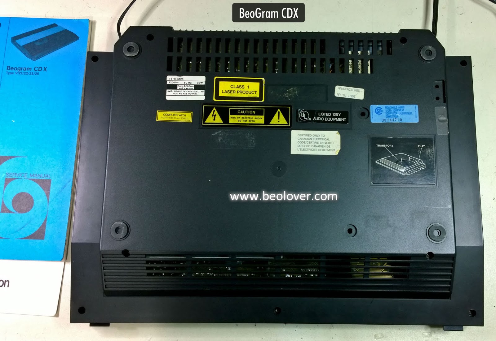
Here is a BeoGram CD X that was recently dropped off to see if I could get it working again.
This is a really nice design by Bang & Olufsen from the mid-eighties, 1986 to be precise.
Interestingly this CD player was marketed for users who did not necessarily own a B&O system. The CD X only has RCA output plugs instead of the usual five or seven pin DIN plug. It also has no remote control capability.
However, when all other CD players were the typical rectangular box shape, B&O went for a nice, sleek, top loading CD player.
Quite a lovely design that I have always liked.
A problem and usually "the problem" with these CD players is that they stop functioning due to problems with vias that connect circuitry to the ground plane of their circuit boards.
That being the case my first task will be to rework all of the board vias and see if that doesn't get this CD X unit working again.
The CD X is not too difficult to figure out how to open up. The service manual has instructional diagrams. The bottom cover is removed first. Then the top can be removed (along with disconnecting a few connections).
Here is the CD X with the bottom cover removed.
Here is the CD X with the top cover removed.
As with most CD X units that have been sitting unused for a while there is quite a bit of dust inside.
I will clean out all of the dust as I work on the two main circuit boards.
I started with the Decoder circuit board (PCB 05) on the underside of the unit. It is probably the key board to repair the vias on.
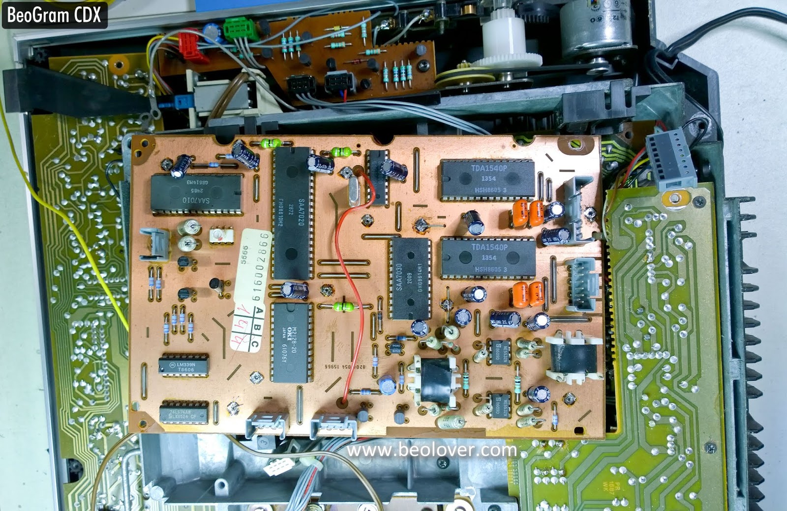
I actually removed this board to do the vias repair.
My repair method is to de-solder the vias, remove the wire/pin and run a piece of stranded wire into the hole. On the ground plane side of the board I fan out the wire strands and solder them to the board.
After that I cut off the new wire on the underside and solder it to the pad on the board.
I apologize for not having photos of the other side of the board and for not taking photos of the other circuit board I reworked the vias on (Servo board - PCB 04). I will make sure to do those for the next CD X unit I work on :-).
After reassembling the CD X I inserted a CD and it played like it should. This CD X unit is working again!
Next was some actual listening testing. I connect the CD X to TP1 of my workshop Beomaster 8000 receiver. The CD X played great.
Being manufactured in 1986 it will likely require some recapping of the electrolytic capacitors at some point. I will also want to replace the belt on the motor that opens and closes the CD X lid. Those tasks will be done in the future.
For now I will move this CD player to a listening room for some more testing before I return it to its owner.
Featured Post
Beolover SyncDrive: DC Platter Motor Replacement for Beogram 4002 and 4004 (Type 551x and 552x)
Late Beogram 4002 and the 4004 (Types 551x and 552x), which have DC platter motors instead of the earlier synchronous AC motors usually suff...
Showing posts with label vias. Show all posts
Saturday, November 9, 2019
Thursday, April 16, 2015
Beomaster 8000: uProcessor Board - Jumpers/Resoldering Vias and Two New Capacitors
The Beomaster 8000 display board that I just restored came with the uProcessor PCB attached. So I checked on the B&O recommended jumpers that bridge the bunch of vias that often go intermittent on these boards. Here is the view from the top after removing the EMI cans:
And from the bottom. It appears that the jumpers were put into place already during an earlier visit to a service department:
I reflowed the vias that they did not cover, and then replaced the two electrolytic capacitors on the board:
After this I replaced the can covers and then cleaned all headers with a fiber glass pen. A thin DeoxIT D100L coat on the header pins finished the job.
Labels:
66LLBM8000,
bang,
Beomaster 8000,
hifi,
jumpers,
olufsen,
PCB,
reflow,
repair,
restoration,
uprocessor,
vias
Tuesday, September 9, 2014
Beomaster 8000: Wire Bridges on Microcomputer Board (#9) and Broken Phono Jack
Before I put the Beomaster 8000 back together for a test-drive in the living room together with his play-pals, the Beocord 9000 and the Beogram 8000, I cleaned and de-oxidized all the contacts on the microcomputer board (PCB #9), and had a look at the inner sanctum, the EMI shielded processor cans. Usually one needs to re-solder the few vias that are on this board, since they tend to be poorly soldered...clearly in the 80's the PCB technology was not that advanced, yet. Anyway, what I found in this particular Beomaster was remarkable. Someone already had put in the B&O recommended wire bridges (and then some...), and they were directly soldered to the processor pins. Unbelievable! Here is a pic:
While the soldering appears to have been carried out with some capability, I would never do it this way...the only parts of the Beomaster 8000 that are truly non-replaceable are the microcontrollers that contain proprietary coding, i.e. one would have to extract the code from a working one, if one would want to attempt replacing it with a NOS chip...
Anyway, clearly, this needs to be left as is. I could not risk to expose those rarefied microcontroller pins to another heat-cool cycle. In a way, since the chips survived this assault, this solution is probably the most reliable...several fewer spring based contacts in between the controllers and their slaves...so I decided to just replace the two electrolytic capacitors on this board and move on.
Here is a pic after putting in the caps:
The last thing that needs to get fixed in this Beomaster is a broken phono jack in the 'socket panel' that lost its tabs that prevent it from popping into the panel when trying to plug in the Beogram:
I am working on a creative solution, since not even Dillen of Beoworld.org has this part available. He said it is rare, since it often breaks...Another day, another 3D print...;-)
Labels:
60DA8000,
bang,
Beogram,
Beomaster 8000,
bridging,
capacitor,
connector,
DIN,
jack,
microcomputer,
microcontroller,
olufsen,
phono,
processor,
repair,
replacement,
restoration,
socket,
vias,
wires
Tuesday, June 10, 2014
Beomaster 8000: Recapping the Caps on the Processor Board (PCB #9) and Via Bypasses
Interesting! When I opened the shield around the processors on PCB #9 of the Beomaster 8000 I am currently restoring, I found this:
Note the green, blue and orange jumpers. They bridge traces that had vias in them on older versions of this board. These vias were not through plated but soldered in instead on those boards and prone to generate open circuits as the solder joints aged. A well-working remedy is to simply re-soldering them. However, I looked into my Bang and Olufsen Service Bulletins folder for the respective bulletin, which actually recommends to bridge them directly between the solder points at the ends of the respective traces. Here it is:
Anyway, this allowed me to directly move on to replacing the two decoupling capacitors on this board. Here is a shot of the board after replacing them:
Next steps are the main reservoir caps and the speaker switches.
Note the green, blue and orange jumpers. They bridge traces that had vias in them on older versions of this board. These vias were not through plated but soldered in instead on those boards and prone to generate open circuits as the solder joints aged. A well-working remedy is to simply re-soldering them. However, I looked into my Bang and Olufsen Service Bulletins folder for the respective bulletin, which actually recommends to bridge them directly between the solder points at the ends of the respective traces. Here it is:
Anyway, this allowed me to directly move on to replacing the two decoupling capacitors on this board. Here is a shot of the board after replacing them:
Next steps are the main reservoir caps and the speaker switches.
Labels:
59MP8000,
bang,
Beomaster 8000,
bypass,
capacitors,
cleaning,
contacts,
olufsen,
recapping,
repair,
restoration,
upgrade,
vias
Subscribe to:
Posts (Atom)