Featured Post

Beolover SyncDrive: DC Platter Motor Replacement for Beogram 4002 and 4004 (Type 551x and 552x)

Late Beogram 4002 and the 4004 (Types 551x and 552x), which have DC platter motors instead of the earlier synchronous AC motors usually suff...

Showing posts with label phono. Show all posts

Thursday, November 17, 2022

Beogram 6000 (5505): Full Functional Restoration Pt.2: Exploration and Restoration of CD-4 Pre-Amplifier

This post is the second installment of my report of the restoration of a Beogram 6000 Type 5505 with AC platter motor. The first part can be found here

What distinguishes a Beogram 6000 from a Beogram 4002 is that it has a CD-4 capable quadraphonic pre-amplifier board factory installed. In many Beogram 4002 such a board could be installed at a later point. CD-4 is mostly interesting from a historical point of view, since this 4-channel format never really took off, and there are not many CD-4 vinyls in circulation.

However, the 6000 has an on-off switch for the CD-4 detection feature, and in off position this pre-amplifier becomes a standard RIAA pre-amp for stereophonic records. This allows connecting a 6000 directly to any standard high-level line input. Many modern receivers do not have a dedicated Phono input anymore, and so getting a 6000 is an interesting option if a classic and/or internal pre-amp design is preferred.

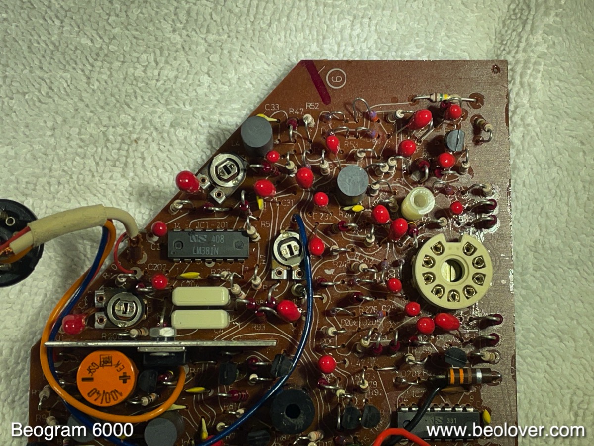
This shows the CD-4 board installed after removing the keypad:

Now that is a pretty 'complex' board! It even has a little board piggy-backed on the part that is located above the keypad. Nowadays a circuit with such functionality would be a single chip with a few external passive components and a power supply. 

Let's have a brief look at the circuit diagram first, the discussion of the restoration follows below. I made an annotated version while trying to understand 'what is what', and which parts are important for the use as RIAA stereo pre-amp.

Here we go: click on the pic and you should be able to see the high-res version and be able to read my comments. Be aware that the comments reflect my 'current state of knowledge' about this board, and should therefore be taken with a grain of salt.

The purple marked/annotated parts are the essential components of the CD-4 detection and demodulation system. The green path is the RIAA stereo signal path through this board. An introduction to CD-4 published in 1973 by JVC can be found here.

In a nutshell, the CD-4 format uses a bandwidth of ~20 to 40kHz to carry two stereo signals, front and rear, which each need ~15kHz bandwidth for high fidelity. It is obvious that a faithful reproduction of frequencies as high as 40kHz requires a high-quality cartridge with a low mass cantilever. The MMC6000 cartridge was dedicated to this format. It has a beryllium cantilever. I think a later MMC20CL with sapphire cantilever could probably also be used. But not sure.

Since we only have one groove, but two sets of signals the signals are encoded as 'sum signal' Front+Rear (F+R) in the audible part of the bandwidth and 'difference signal' Front-Rear (F-R) in the >20kHz range. The F+R signal is pre-emphasized in accordance with the RIAA curve and essentially 'put into the groove' like a conventional stereo signal. For this reason CD-4 records are compatible with standard stereo players. One just does cannot distinguish the rear channels.
The F-R signal, in contrast, is not pre-emphasized, and it is superimposed to the F+R signal as a frequency-modulated signal around a 30kHz carrier tone. Sort of like a FM radio signal, just with a carrier that is much closer to the modulated audio signal. Due to the high-frequency bandwidth of the F-R signal it is much more affected by noise from the vinyl surface and preamp etc...This made it necessary to use noise-suppression for this signal. This is done with a system that works similar to Dolby used on tape decks. JVC called their system ANRS. The principle is similar to the Dolby systems: the volume range is compressed for recording, and then decompressed during play. This reduces the noise level for low-volume sections.

Let's see what happens with the signal from the cartridge in the circuit:

The diagram shows only the left channel, as well as the circuitry that is used by both channels. The signal from the cartridge enters the circuit via the coupling capacitor 6C2 into the opamp 6IC1. There it receives a 40-50dBV boost and is also RIAA de-emphasized in the low frequency range via the filter 6C1 and 6R5 in the feedback circuit. This does not affect the high-frequency F-R part of the signal, therefore it can be done for the entire signal right in the opamp. 

After the opamp, however, the signal gets split up into F+R and F-R.

1) F-R:
After the opamp the signal goes through a band-pass filter to get rid of F+R and then enters a demodulation circuit (annotated purple) that works similar to a FM radio receiver followed by the ANRS noise reduction decompressor. At the end of the process the F-R signal is reconstituted in the audible spectrum ("B" in the diagram) and enters the "matrix" where it is combined with the F+R signal and then F and R are spit out separately. The matrix does this by adding the F-R signal to F+R and also  the inverted (180 deg phase shifted) F-R = -F+R signal to F+R. So we get F+R+F-R = 2F and F+R-F+R = 2R. All of this of course in stereo. So at the end we have the front channels FR and FL, and the rear channels RR and RL.

2) F+R:

After the opamp, the signal is also sent through a low pass 6R7/6C4 which does the second half of the RIAA deemphasizing. This path is marked green. The signal then goes through the decoupling capacitors 6C31 and 6C32. In between the two capacitors the signal is diverted into a filter formed by 6L4/6C33/6R47 which essentially removes any trace of the F-R signal, and then feeds the F+R signal into the matrix for reconstitution of separate F and R channels.

What happens with a conventional stereo signal?

If there is only a stereo signal from a conventional record, the signal is routed further along the green path, which basically sends the signal unmodified to the output socket. Of course it also goes through the filter and the F+R section, but in the case of regular stereo the matrix signal is stopped via the diode switch es from reaching the output socket - see below.

How does the circuit make sure that a regular stereo signal does not get messed with in the matrix circuit?

This is basically done by the 'diode switch' comprised of the diodes around the matrix. Depending on how these diodes are biased the signal either travels the green path or the decoded CD-4 signal gets routed to the output socket.
The diode switch is controlled by the "frequency-to-DC-converter" (blue frame on the left) and the Schmitt trigger circuit (red frame next to it). Basically, the frequency-to-DC-converter produces a DC output voltage at the emitter of 6TR1 that is low (0V) if there is no CD-4 carrier tone, and high (3.8V) if there is one. This signal then gets fed into the Schmitt trigger which has two outputs A and B. If CD-4 is detected A is high and B is low, while if there is a regular stereo record we get the reverse output.

Both A and B low mutes the entire output. This is done via the muting circuit, which essentially overrides the Schmitt trigger by pulling both outputs A and B low via 6D17 and 6D18 when the arm is up.

The great thing (for using it as a regular RIAA pre-amp) about this circuit is that, with the CD-4 switch on the right side of the Beogram enclosure (added in red to the frequency-to-DC-converter circuit), one can pull the base of 6TR11 permanently to GND. This configures the Schmitt trigger permanently to its no CD-4 setting, B=high and A=low, and then all records are played like stereo records. In other words the signal follows the green route. While this should happen automatically, I think B&O added the switch to make sure one can set the patch to regular stereo incase there is a 'misunderstanding' in the detection circuit. After all we are talking about a 'complex analog audio system'...;-).

Restoration of the board:

This shows the board after extraction:
And here the upper section after removing the piggy-backed smaller board:
I replaced all the electrolytic capacitors on the board. The ones in the 'stereo signal path' were replaced with fitting WIMA foil capacitors to reduce distortions: 
Pretty! They know exactly why they package them in these pretty red little boxes!...;-)
I also replaced the CD 4 indicator lamp with a LED. If you use a high output LED that only needs a small current to light up, then you may want to add a ~3k resistor between the base of 6TR14 and GND to pull the base down sufficiently to turn the lamp off when there is no CD-4 signal/the switch is turned to OFF. I did that with a SMD resistor on the solder side of the board at a convenient location that could be bridged by the resistor. The blue resistor seen in the picture is the current limiting resistor for the LED to make it compatible with the 22.8V rail:
This shows the restored board
and the removed parts.
Quite a few electrolytic capacitors in this historic analog design! While in there I also added a switch in the back allowing connecting the output cable shield to the signal ground in case there is a hum issue:
This is where the other end of the switch connects at the output plug. I added it to the pin where the inner braid is connected:
This shows the board installed again:
After this I put the keypad back in place and did some listening. Unfortunately, I was able to hear some motor noise in the speakers when cranking up the volume with the arm down next to the platter.
Not too unexpected in a design like this since motors introduce a lot of noise on power rails, while the RIAA amp is very sensitive to small signals.

This was confirmed by a measurement with my Quant Asylum QA400 audio analyzer. The red trace shows the noise spectrum with the arm down after I put the Beogram back on the bench (note that this spectrum is shifted 20dBV higher to separate it from the blue spectrum that was measured after my fix was implemented). Most of these peaks, except the one at 60Hz come from the motor.
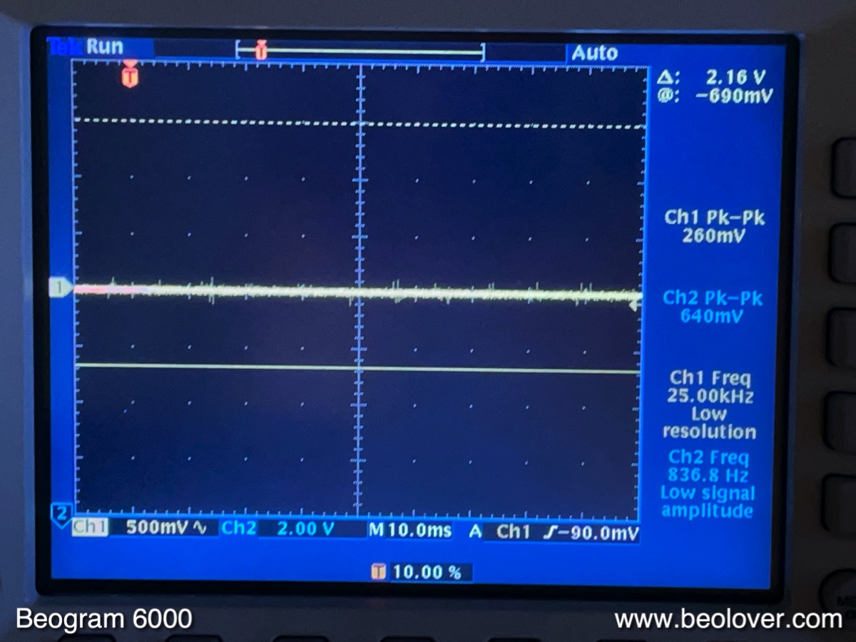
I hooked up the oscilloscope to the 30V rail (orange wires on 3300uF capacitors) and saw this (using AC coupling):
~500mV noise!

So I did two things:
First I converted the power supply of the CD-4 board from 'main PCB 22.8V rail referenced' to a 24V Zener reference. This is easy to do on this board. This shows the original power supply section of the board. The big capacitor is 6C94:
I removed this capacitor and implemented a 24V Zener diode in its place. In combination with 6R96 and 6R98 this created the classic Zener voltage divider to be fed into the base of an emitter-follower like 6TR17. One more thing had to be done to 'disconnect' the blue wire that is the 'reference' to the 22.8V rail of the main board. I did this by removing 6D20 while leaving the blue wire in place. This shows the section in its final configuration:
The second step I took was to implement a 'capacitance multiplier' in front of the two 3300uV reservoir capacitors:
Basically, at the positive terminals of the capacitors the orange wire from the emitter of 0TR1 feeds the regulated voltage to the capacitor. In the original configuration, a second orange wire then connects to the rest of the circuit. In my modification the orange wire now connects to the output of the capacitance multiplier and the input to the capacitors.
This is how the voltage looked after the added circuit:

Much nicer! And when I measured the noise spectrum, I got the blue trace in the above graph. You see that most peaks are gone. Only the usual 60Hz interference and a couple smaller peaks are left. 

How does a 'capacitance multiplier' work? Essentially it is a bit of a misnomer, since it is rather an emitter follower that is referenced to a very low pass filtered (2k/100uF) low-current version of the original to be cleaned up voltage rail. Since the emitter follows the signal at the filter output, it removes all the high frequency stuff on the power rail. There is a great Dave video on the EEVblog that explains all the ways to remove ripple and noise. I built it with a TIP102 Darlington to get a big gain, which allows to reduce the cutoff frequency even more since the current in the filter output can be very small while still being able to drive a large current to the load. This shows a simulation of my little circuit in iCircuit:
I assumed a 40V DC signal with a 1Vpp ripple on it (green) and a 1000x gain for the transistor, similar to a Darlington. The circuit cleaned this up to the yellow trace which has a 13mV ripple. So basically a two magnitudes improvement.

I listened to the deck again, and only a healthy RIAA pre-amp hiss came from the speakers when cranking up the amplifier with the arm down next to the platter! Beolovely!

My final act was to try measuring the total harmonic distortion (THD) and THD+noise (THD+N) of this RIAA amplifier using the QA400, which can calculate it from the FFT spectrum. THD numbers are always a bit ambiguous when reading manufacturer specifications since it is never stated under what conditions they were measured. So it may be difficult to directly compare my measurements with others. Therefore, I post the spectra that I measured along with the calculated numbers. 
The QA400 outputs were connected with a BNC-to-minigrabber cable directly to the Left and Right Channel pins at the input plug of the CD-4 board. Then the deck was turned on at 33 RPM and the arm lowered to open up the signal path through the diode switch. The CD-4 switch was set to OFF. 
I did two measurements for two input levels, -60dBV and -70dBV. These levels correspond to 14mVmax/10mVrms and 4.4mVmax/3.16mVrms respectively signals. I measured a few MMC cartridges a while back and they produced such levels during fairly loud passages.
The first graph shows the -60dBV curve. Right and left looked fairly similar, so I am only showing the right one for clarity. The signal strength of the amplified 1kHz tone is about -17dBV, i.e. we have an amplification at 1kHz of about 43 dBV. This gain resulted by setting the two gain trimmers in the opamp feedback to center position. For this spectrum the QA400 calculated THD=0.46% and THD+N=0.52%.


The second graph shows the same measurement at the lower -70dBV input level. It is obvious that the harmonics went down, and consequently the THD numbers are lower with THD=0.14. THD+N=0.8 is higher since the signal to noise ratio is now 10dB worse.
These THD values are considerably higher than what is stated for modern external RIAA pre-amps, which usually seem to be in the 0.0X% range at similar gains.
In my opinion this does not matter much since cartridges and the records themselves usually have much higher distortion levels, i.e. the small amounts added by this classic RIAA design will not matter much. I really like listening to this Beogram 6000. It sounds very nicely and gives you that awesome 1970s warmth that makes you think of bellbottoms and brown corduroy suits with wide lapels!...;-)


Monday, November 26, 2018

Beomaster 8000: Exchanging the Opamps in the Signal Path and Test

After updating the uProcessor board in the Beomaster 8000 that I am working on right now, it was decided to also update the opamps while the unit was in service position. We recently noticed that the opamps in the signal path of the Beomaster 8000 can degrade resulting in increased distortions (THD), i.e. it is a good idea to also replace the opamps when the boards are out for restoration. Here we go:

This shows the control panel PCB before the upgrade:
Most of the 8-pin ICs on this board are signal path opamps. This shows the board with new socketed LF535 opamps installed:


On to the preamp/input board. I forgot to take a picture of the original condition of the board. Here are a couple shots of the board after replacing the opamps with socketed LF353 units (except the phono input, which was replaced with a low noise LM833 type):
A detail photo of the phono pre-amp section:
After implanting the boards I characterized the performance of the unit with my QA400 audio analyzer. The bandwidth curve yielded the spec -1 dBV drop between 100 and 20,000Hz, and the total harmonic distortion (THD) values at volume 5.0 (just below clipping) were 0.008% on both channels, which is consistent with other Beomaster 8000s we measured. See here for a detailed discussion of such measurements. So far so good...the unit went on into our living room to see if the performance of this Beomaster 8000 is consistent in day-to-day operation.


Wednesday, April 18, 2018

Beomaster 8000: New Signal Path Opamps and Amplifier Performance Characterization with a QA400 Audio Analyzer

Inspired by Sonavor's recent effort to characterize the amplifier performance of a Beomaster 8000 after replacing all signal path opamps, my Australian customer asked that the same would be done to his 8000 before sending it back (after upgrading its circuit with a muting function for the FM section while the Phono input is selected to eliminate crosstalk).

And I am glad he asked. It turns out that it is a great idea to replace the opamps when performing a full restoration of the Beomaster 8000. My measurements yielded a 14 dBV improvement of the THD (Total Harmonic Distortion) performance on the left channel after implementing new opamps.

This shows the preamplifier and input selector board with the original opamps in place:
and after replacing them with new LF353 units (except the phono input, which was replaced with a low noise LM833 type):
I used IC sockets to spare the opamps the stress of soldering. Probably not necessary, but then why not. I did the same for the control panel PCB. This shows it with new LF353s in place:
After putting the control panel back together I performed a series of measurements to see if the amplifier performance would measure up to the values given in the service manual. It turned out that such a comparison is difficult to make due to the inherently different measurement methodology used in the 80s and with the instrumentation that is available today. But I think the measurements below show that this 8000 is now in good shape.

Let the fun begin:
I use a Quant Asylum QA400 audio analyzer for such measurements. Essentially this device yields a Fast Fourier Transform (FFT) of the audio signal that is put into it, and it can perform some measurements (i.e. calculations on the FFT spectrum) based on that data. The measurements include power, total harmonic distortion, signal-to-noise, and frequency response. 
Let's have a look at the output spectrum measured with a 0 dBV 1 kHz signal at the Tape 1 input of the Beomaster:

The dBV values essentially give the amplitude ('level') of the signal relative to a standard 1Vrms signal V0. Since level=20*log(V/V0), a signal change of 20dBV corresponds to a 10x change of the amplitude. As an example, if the measured amplitude of the 1kHz signal at the output of the amplifier is 10 Vrms with an input signal of 1 Vrms from the waveform generator, then level=20*log(10/1)=20*1=20 dBV. If the output signal were 100 Vrms, the level gain would be 40 dBV and so on.

Looking at the spectrum above, you probably wondered why the 1 kHz peak is only at about -8 dBV, while the amplifier operated at a volume setting of 5.0, which is close to the maximum output amplitude it can muster. The reason is that the measurement was performed via a voltage divider that was connected as load at the output of the amplifier. The divider was built from two 4 Ohm 50W power resistors and a 0.1 Ohm 3W resistor in series. This shows the setup:
Since the Beomaster is able to produce 100W output power into an 8 Ohm load, the resistors need to be mounted on a heat sink. I used a RF amplifier can that I had laying around from another project. The Y-shaped red wires that are soldered to the small 0.1 Ohm resistor connect to the BNC jack on the right side of the RF can, which then is connected to the QA400 input. The resistor chain is connected on the left to the speaker jack of the Beomaster. This setup guarantees that the QA400 input never gets more than about 1 Vpp. But it also means that the output amplitude that the QA400 'sees' is only 1/81th of the actual amplitude that is applied across the 8.1 Ohms. 
Using the above level=20*log(V/V0) formula, we can calculate that the level difference due to the voltage divider is about -38dBV (20*log(1/81)=-38.17 dBV). This means that the 1 kHz peak in the above graph would be at ~-8+38dBV=~+30dBV. I could have shifted the peaks in the graph, but since all measurements that are performed are inherently differences between two levels, this shift really does not matter, i.e. in the following all levels are just as they came out of the QA400, i.e. -38dBV lower than the real signals.

So what do we see in the above spectra? Mainly the THD spectrum to the left of the main 1 kHz peak and some noise. We can see that the 1st harmonic at 2 kHz is about -84 dBV weaker than the main peak. According to the above calculation, this means that the amplitude of that distortion is about 10^4 (= 10,000) times weaker than the main signal. Well below what a human ear could notice. The -84 dBV value is close to the THD measurement result of the QA400, which came in at about -82 dBV (=0.008%). The measurement is a bit worse than the 84 dBV value determined from the graph since there are higher order THD peaks that add to the total distortion. This was the only measurement result that changed before and after replacing the opamps in the signal path. My initial measurements of the left channel yielded a measly -68 dBV THD value, and after the opamp exchange this was improved to -82 dBV. So I think it is a great idea to replace all opamps when the boards are upgraded with new capacitors, just to be on the safe side.

So how does this value compare to the THD value from the Beomaster 8000 service manual? The value stated there is "< 0.05%". So we could be happy and say: "Wow this 8000 is almost 10x better than the value in the manual!". Not so fast, I would think, since the manual states that the measurements were performed according to the "IHF A-202" standard. At this point I do not know what this means, i.e. we need to postpone this comparison with the stated values. But I think we can confidently say that this Beomaster is performing reasonably well and is probably within the original specifications.

Another interesting measurement to perform on an amplifier is its signal to noise (SNR) ratio. This essentially gives us a number that qualifies how much stronger the signal is relative to the noise ("hiss") of the amplifier. This measurement is a bit more difficult to do and understand since we are comparing a defined signal peak amplitude (or power) with a diffuse noise background that is composed of a continuum of frequencies spanning the entire audible range and beyond.

I played a bit with the QA400 settings and it turned out that the SNR measurement is strongly dependent on the number of samples used for the FFT transformation of the input signal. I was able to "change" the SNR value from 65 dBV to 88 dBV simply by changing the FFT resolution from 8196 samples to 65535 samples. This means that depending on the setting the SNR value changed by a factor of 10, one full magnitude. So what is happening? A bit of reading up on the internet and a semi-cryptic response from the Quant Asylum tech support suggested that at lower FFT resolutions the main 1 kHz peak spreads out over several 'frequency bins', thereby lifting the spectral power outside the 1 kHz line, which is misunderstood by the FFT algorithm as part of the noise. This means that at higher FFT resolutions this 'frequency spill out' becomes less pronounced. So we can assume that the higher value is closer to the true value, even though the true value may be even better. Unfortunately the QA400 can only go to 65535 samples, i.e. we would need to find better equipment for an answer. 
Wondering about this topic, I performed an experiment that would allow me circumventing the FFT based calculation of the SNR. I measured the signal power of the spectrum at various FFT resolutions and it turned out that the PWR value is not significantly dependent on the resolution. This makes sense since PWR measures the power of the entire spectrum, i.e. integrates over the entire frequency range. So resolution is of limited importance, as long as the signal peak is still 'caught' in one of the sampled frequency bins.
This realization enables a basic SNR measurement: Measure the PWR value with the signal present at the amplifier input and then ground the input and measure again. Subtract the two values and the SNR is obtained.
My measurements yielded on both channels -8 dBV with 1 kHz signal (at Volume setting 5.0) and -98 dBV with the input grounded (also at Volume 5.0). The difference is 90 dBV, a bit better than the best 88 dBV value measured via FFT analysis. This compares to a ">77 dB" stated in the service manual. Again, we do not really know at this point how the 77 dB value was measured, but I think we are on the safe side and can conclude that this Beomaster 8000 is operating on spec.

Another interesting measurement is the frequency response ("FR"). The QA400 does this measurement by sending a square pulse into the input of the amplifier and then measuring the response at the output. Since a square pulse contains all wavelengths, the FFT of the response yields a true spectrum of the amplifier FR. I verified this by manually measuring the transmission for a few frequencies and the FR curves were exactly matched, i.e. I think we can believe this measurement as it comes out of the QA400. This shows the FR spectrum measured on both channels:
I cut the spectrum off at 1 kHz since there was some 60 Hz noise, and the FR drop at 20 kHz seems typically referenced to 1 kHz. So what we see from the graph is that there is a 1 dBV drop from 1 kHz to 20 kHz. The manual prescribes 0.5 dBV, but of course, again, we do not know how this was measured etc...A difference of 0.5 dBV corresponds to a signal ratio of 10^(0.5/20)=1.06, i.e. the signal at 20 kHz is 6% smaller than it should be. Not very dramatic, and most likely this discrepancy is a result of the different measurement methodologies that were applied in the 80s.

Since everything was hooked up, I decided to measure the FRs for the various filters the 8000 has. This shows the spectra:
The spectra show the FR for filter 1, 2 and both active, for bass and treble sliders set to minimum and maximum, and the flat (filter button "off") response in direct comparison. We can see nicely that the treble and bass sliders allow a ~±10 dBV change of the higher and lower frequency ranges, and that the filters cut off around 7 kHz and 10 kHz at  as prescribed in the manual.

So in summary, I think we can say that this Beomaster is in excellent condition and that everything works as it should.


Friday, February 9, 2018

Beomaster 8000 Circuit Upgrade: FM Audio Muting During Use of Phono Input

After reviving the Beomaster 8000 that came for a visit from Australia with new processor crystals, it was time to do some additional work on it. My customer was annoyed by the crosstalk between FM audio and the phono input while listening to vinyls records, and a solution to alleviate this issue was requested.

Phono inputs are especially susceptible to crosstalk since they are about 100 times more sensitive than regular high level line inputs. The result is that when the phono input is selected (with a player attached or grounded inputs) the FM audio signal can be heard weakly in the background (if a station is dialed in). And that is of course not very Beolovely. The reason for this behavior is a design flaw in the Beomaster circuit: When another input than FM is selected and previously a station was tuned in the FM tuner stays on and continues blasting its signal out to the amplifier board, even though one wants to listen to a record via the phono input.

This diagram shows the solution I developed after a bit of head scratching and downloading the data sheet for the CA3189E IF stage integrated circuit.


The CA3189E chip is responsible for shifting the audio modulation of the FM signal that is received in the front end of the tuner to a lower frequency and amplifying it before the audio signal is then extracted in the detector. The CA3189E was designed with radio applications in mind that do not have a microcontroller at their disposal. The Beomaster mutes the FM audio while tuning between stations to prevent the speakers from emitting loud static noise. It does that by extracting signal strength information from the CA3189E via pins 13 (TP22) and 12, and feeding it into the microcontroller after processing in some additional circuitry. The microcontroller then decides when to ramp the output volume down using the main volume attenuators. 
Alternatively, this chip can do this on its own via its audio mute input (pin 5). The CA3189E data sheet contains a circuit that shows how to do this if you are interested. In the Beomaster 8000 design this pin is simply grounded via R37 to permanently turn the signal output on. 

The circuit on the data sheet in combination with some measurements of the signal strength related output of pin 12 (it seems to be close to 0V between stations and at about 5V with a strong FM station dialed in) suggested that pin 5 could be controlled directly via the microcontroller signal that is fed into the two AD10/278 input selector chips on the preamplifier board. The AD10/278s have three inputs for selecting FM, Tape 2 and Phono. When one selects one of these inputs on the control panel of the Beomaster 8000, the corresponding input goes high (~4.8V), activating that particular signal path on the chips. So my idea was to simply connect the Phono selector line to the audio mute input of the CA3189E via R37 after severing the ground connection of R37 by unsoldering the resistor on the ground facing end. That way, whenever Phono is selected the FM audio muting circuit is automatically activated muting any FM audio in the system that could crosstalk with the phono input.

This shows the practical implementation of this scheme. I elected to make the AD10/278 connector directly at the ribbon cable coming from the microcontroller board. That way the additional connection can be removed from the amplifier board when it needs to be taken out.
I soldered the jumper wire to the plug contacts
and then modified the black cap with a bit of Dremeling to fit over the jumper wire:
Then I wrapped the plug with some electrical tape to keep the jumper wire from moving so it will not break off. This shows the plug plugged in next to one of the AD10/278:
I connected the other end of the jumper to the disconnected end of the R37 resistor after securing it with some shrink tubing to the capacitor located next to it. The solder spot was secured by some additional white shrink tubing:
And then it was time to turn the Beomaster back on. And it seems to work smoothly. FM still works and when Phono is selected there is no more FM audio superimposed. Beolovely!

Saturday, January 27, 2018

Beogram 4002 (5513): Installation of Beolover Commander MkII Remote and Internal RIAA Pre-Amp Board

The owner of the Beogram 4002 (5513) that I am finishing up asked me to install my 4002 Commander remote control as well as my internal RIAA pre-amplifier module. The Commander allows the full control of the 4002 with an Apple remote, while the RIAA gives the Beogram a high level output that can be directly plugged into any CD/DVD/AUX input on modern amplifiers. 
This shows the RIAA board together with the mounting adapter that elevates it above the headers on the output PCB:
This shows the board installed:
It is soldered into the spot where the output relay is located. The RIAA board design includes a second output relay for the non-amplified signal path, i.e. the RIAA can taken out of the signal path by simply plugging the two plugs into the original headers. See here for more detail about the RIAA board design and use. 

This shows the Commander MkII receiver unit on the bench:
The extension to the right is the IR receiver that feeds through in between the plinth and the enclosure to the outside of the deck. The MkII version has an added auto repeat function which uses a red LED (extension to the left) to indicate the auto-repeat status (LED permanently on: One time repeat, blinking: up to 10 plays and off: no auto repeat). This LED is installed beneath the CD-4 indicator in the RPM adjustment panel. This can be seen here:
The Commander board itself just plugs into the keypad connector, while the keypad plugs into a header on the Commander. One of the four screws that hold the main PCB in place doubles to hold the Commander PCB piggybacking on top of the main PCB.
On to the final adjustments and a test drive!


Monday, October 30, 2017

Beogram 4002 (5523): Installation of 4002 Commander MkII Remote Control and Internal RIAA Preamp

I recently finished up the restoration of a Beogram 4002 (5523). My customer decided to add both the Beolover 4002 Commander MkII remote control receiver (it works together with a matched Apple remote) and the internal RIAA pre-amplifier. I developed these two upgrades a while ago. More information about their performance and installation is given on the 4002 Commander page on the blog and in this post about the development of the RIAA amp.  Both boards are available to other enthusiasts. Just send an email or use the contact form on the right. 

This shows the two boards together:
The board at the bottom of the picture is the Commander MkII remote receiver board. The MkII version comes with a repeat function, which uses the CD4 indicator on the keypad cluster as indictor. It is a plug-and-play installation. The board installs into the keyboard header on the main PCB and is bolted into place using one of the screws that holds the PCB down. 
The RIAA amplifier is soldered directly into the output relay solder points. This shows the output board as I rebuilt it with a new relay and grounding switch:
For the installation of the RIAA amp I needed to remove the relay and the switch again to make space for the board and the connectors. This shows the output PCB prepared for the installation together with the RIAA board upside down:
The red 3D printed component serves as spacer to elevate the board above the black in- and output board headers. This shows the board after installation:
The original headers are still accessible, i.e. the Beogram can easily be configured in its original way by plugging the cables into the original headers instead of the white amplifier connectors.
This shows both installed in the Beogram:


Friday, April 21, 2017

Beogram 6000 (5512): Restoration and Characterization of CD-4 RIAA Preamplifier

The most interesting part of the restoration of the Beogram 6000 that is on my bench right now was  working on the 4-channel CD-4 preamplifier board. This board renders the 6000 capable of reproducing CD-4 quadraphonic vinyls from the 70s. While there are not so many CD-4 vinyls that were cut for this short-lived format, this preamplifier board is also a veritable stereo preamp, which is very convenient if the Beogram is to be used with a modern amplifier (who often do not have Phono input stages anymore). The CD-4 board allows connecting the Beogram to any standard high level input like a DVD or AUX input.

The first step was to replace all the electrolytic capacitors on this board. This shows the board in the turntable after taking the keypad out:
I removed the board
and then replaced the capacitors and the indicator light bulb:
The light bulb can be replaced with a standard red LED and a 1k resistor:
This is how the LED peeks out through the cutout in the keypad that permits its light into the CD-4 indicator:
This shows the CD-4 preamp in action playing my The Fisher CD-4 test record (my only CD-4 record):

The more interesting part here is however: How well does this preamp perform for listening to stereo records. The most important items here are how much noise is added and how faithfully does it deemphasize the RIAA curve. I connected the Beogram DIN5 to my QA400 audio analyzer and measured a noise spectrum:
These curves were measured for the left and right channels. They look quite identical. They were measured with a cartridge installed and the turntable running with the arm lowered next to the platter. 

This made sure that the measurement was performed with the motor running to see if there is any crosstalk through the power supply of the Beogram from the motor (there is not) and that the preamp was actually amplifying the signal from the cartridge. When the arm is up the signal in the preamp is grounded, i.e. one only sees the noise from the amplifier itself. This is a boring measurement, which yielded for this CD-4 preamp a flat line at about -130dBV. This number corresponds to the noise numbers that are often given for external phono preamps that are sold for considerable amounts of money. -130dBV is a big negative number and impressive. However, it is meaningless for any practical use of a phono preamp. The measurement shown above is much more crucial, since it gives the noise floor defined by the cartridge, which is what you hear when a record is played.

What we see from the graph is that the 1kHz noise is about -110dBV. Considering that a 0VU level  is at about -20dBV, we can say that with this amplifier and a cartridge we have about 90dBV maximum signal-to-noise. What does this mean in practical terms? 20dBV correspond to a 10x difference in the amplitude of the signal, i.e. 90dB means that the noise contributed by the cartridge is less than 1/1000th of the audio signal at the highest level. 

You may wonder why I stopped writing about the amplifier noise and just mention the cartridge. Well, the amplifier noise is -130dB, i.e. it is another factor 10 smaller than the cartridge noise, i.e. pretty irrelevant at this point. 

An interesting question is: Why does the cartridge make most of the noise? (actually not-the vinyl surface is even more noisy than anything 'electronic' I am discussing here...see my discussion of the BeoloverRIAA internal amplifier for the Beogram 4002
After all it is a passive component that has no active (powered) electronic components, except one coil per channel that picks up the signal from the moving magnet connected to the needle. Here is where physics comes in: All conductors generate Johnson-Nyquist noise, which is generated by thermal movement of electrons in the conductor. This movement is random in direction, i.e. the electrons move forth and back at high speed through the wires of the cartridge coils and the connecting leads, which generates a small fluctuating current that is permanently fed into the amplifier input, hence one can hear a bit of hiss (white noise) even if the needle does not touch the platter.

One more interesting question: Why is the noise in the above spectrum higher at low frequencies than at higher frequencies? The answer is: This is a direct consequence of the RIAA deemphasis of the amplifier. Records are recorded in a way that low frequencies are engraved at a lower amplitude than higher frequencies. The reason is that lower frequencies need larger 'wiggles' in the groove to generate the same acceleration of the magnets (=mV output signal from the cartridge) like higher frequencies at the same audio volume. This trick allows to squeeze the grooves closer together and more music can be put on a side of a record. This shows the theoretical RIAA curve (from wikipedia):
The red curve is the playback curve. So if we have a flat noise spectrum (white noise) coming from the cartridge, the spectrum should drop by about -40dBV across the 20Hz-to-20kHz range. And that is what we see in the above measurement. The drop is about -36dBV, i.e. the RIAA deemphasis of the CD-4 board is slightly off from the theoretical curve from wikipedia. This difference, however, is pretty irrelevant in practical terms since a) -4 dBV it is hardly discernible when listening to music, and b) the RIAA emphasis (blue curve) of records from different labels are all somewhat different, too, i.e. they use different RIAA curves to begin with.
One last point: I just assumed that the noise coming from the cartridge is 'white', i.e. flat. Is this really the case? Yes, it appears so. Thermal noise is constant per frequency up to the GHz range:
This graph was taken from this interesting webpage, where thermal noise is discussed in some detail. This means that, in absence of a white noise generator, using a cartridge connected to the pre-amp seems to be a pretty decent way for measuring the quality of the RIAA deemphasis of an amplifier. 

Another interesting point here is that the thermal noise level depends on the resistance of the conductor that produces it. Hence, shorting the input of an amplifier connects essentially 0 Ohms, which kills most of the noise at the input, and one then measures only the noise generated within the amplifier.

Allright...after this little excursion into the land of physics, it is time to put this Beogram back together, do some final adjustments and then finally enjoy some lovely vinyl! This time through the line-level Phono4 input of my Beomaster 6000. Exciting prospects!