This post is the second installment of my report of the restoration of a Beogram 6000 Type 5505 with AC platter motor. The first part can be found here.
What distinguishes a Beogram 6000 from a Beogram 4002 is that it has a CD-4 capable quadraphonic pre-amplifier board factory installed. In many Beogram 4002 such a board could be installed at a later point. CD-4 is mostly interesting from a historical point of view, since this 4-channel format never really took off, and there are not many CD-4 vinyls in circulation.
However, the 6000 has an on-off switch for the CD-4 detection feature, and in off position this pre-amplifier becomes a standard RIAA pre-amp for stereophonic records. This allows connecting a 6000 directly to any standard high-level line input. Many modern receivers do not have a dedicated Phono input anymore, and so getting a 6000 is an interesting option if a classic and/or internal pre-amp design is preferred.
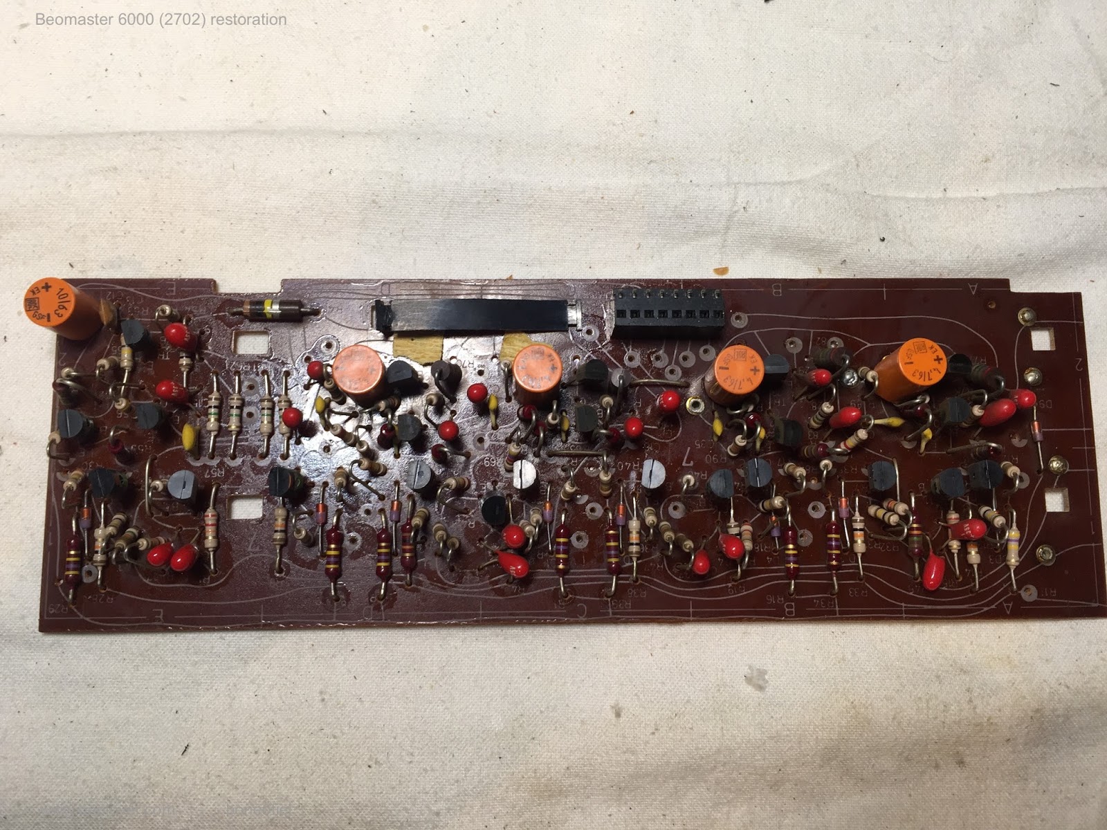
This shows the CD-4 board installed after removing the keypad:
Now that is a pretty 'complex' board! It even has a little board piggy-backed on the part that is located above the keypad. Nowadays a circuit with such functionality would be a single chip with a few external passive components and a power supply.
Let's have a brief look at the circuit diagram first, the discussion of the restoration follows below. I made an annotated version while trying to understand 'what is what', and which parts are important for the use as RIAA stereo pre-amp.
Here we go: click on the pic and you should be able to see the high-res version and be able to read my comments. Be aware that the comments reflect my 'current state of knowledge' about this board, and should therefore be taken with a grain of salt.
The purple marked/annotated parts are the essential components of the CD-4 detection and demodulation system. The green path is the RIAA stereo signal path through this board. An introduction to CD-4 published in 1973 by JVC can be found
here.
In a nutshell, the CD-4 format uses a bandwidth of ~20 to 40kHz to carry two stereo signals, front and rear, which each need ~15kHz bandwidth for high fidelity. It is obvious that a faithful reproduction of frequencies as high as 40kHz requires a high-quality cartridge with a low mass cantilever. The
MMC6000 cartridge was dedicated to this format. It has a beryllium cantilever. I think a later
MMC20CL with sapphire cantilever could probably also be used. But not sure.
Since we only have one groove, but two sets of signals the signals are encoded as 'sum signal' Front+Rear (F+R) in the audible part of the bandwidth and 'difference signal' Front-Rear (F-R) in the >20kHz range. The F+R signal is pre-emphasized in accordance with the RIAA curve and essentially 'put into the groove' like a conventional stereo signal. For this reason CD-4 records are compatible with standard stereo players. One just does cannot distinguish the rear channels.
The F-R signal, in contrast, is not pre-emphasized, and it is superimposed to the F+R signal as a frequency-modulated signal around a 30kHz carrier tone. Sort of like a FM radio signal, just with a carrier that is much closer to the modulated audio signal. Due to the high-frequency bandwidth of the F-R signal it is much more affected by noise from the vinyl surface and preamp etc...This made it necessary to use noise-suppression for this signal. This is done with a system that works similar to Dolby used on tape decks. JVC called their system ANRS. The principle is similar to the Dolby systems: the volume range is compressed for recording, and then decompressed during play. This reduces the noise level for low-volume sections.
Let's see what happens with the signal from the cartridge in the circuit:
The diagram shows only the left channel, as well as the circuitry that is used by both channels. The signal from the cartridge enters the circuit via the coupling capacitor 6C2 into the opamp 6IC1. There it receives a 40-50dBV boost and is also RIAA de-emphasized in the low frequency range via the filter 6C1 and 6R5 in the feedback circuit. This does not affect the high-frequency F-R part of the signal, therefore it can be done for the entire signal right in the opamp.
After the opamp, however, the signal gets split up into F+R and F-R.
1) F-R:
After the opamp the signal goes through a band-pass filter to get rid of F+R and then enters a demodulation circuit (annotated purple) that works similar to a FM radio receiver followed by the ANRS noise reduction decompressor. At the end of the process the F-R signal is reconstituted in the audible spectrum ("B" in the diagram) and enters the "matrix" where it is combined with the F+R signal and then F and R are spit out separately. The matrix does this by adding the F-R signal to F+R and also the inverted (180 deg phase shifted) F-R = -F+R signal to F+R. So we get F+R+F-R = 2F and F+R-F+R = 2R. All of this of course in stereo. So at the end we have the front channels FR and FL, and the rear channels RR and RL.
2) F+R:
After the opamp, the signal is also sent through a low pass 6R7/6C4 which does the second half of the RIAA deemphasizing. This path is marked green. The signal then goes through the decoupling capacitors 6C31 and 6C32. In between the two capacitors the signal is diverted into a filter formed by 6L4/6C33/6R47 which essentially removes any trace of the F-R signal, and then feeds the F+R signal into the matrix for reconstitution of separate F and R channels.
What happens with a conventional stereo signal?
If there is only a stereo signal from a conventional record, the signal is routed further along the green path, which basically sends the signal unmodified to the output socket. Of course it also goes through the filter and the F+R section, but in the case of regular stereo the matrix signal is stopped via the diode switch es from reaching the output socket - see below.
How does the circuit make sure that a regular stereo signal does not get messed with in the matrix circuit?
This is basically done by the 'diode switch' comprised of the diodes around the matrix. Depending on how these diodes are biased the signal either travels the green path or the decoded CD-4 signal gets routed to the output socket.
The diode switch is controlled by the "frequency-to-DC-converter" (blue frame on the left) and the Schmitt trigger circuit (red frame next to it). Basically, the frequency-to-DC-converter produces a DC output voltage at the emitter of 6TR1 that is low (0V) if there is no CD-4 carrier tone, and high (3.8V) if there is one. This signal then gets fed into the Schmitt trigger which has two outputs A and B. If CD-4 is detected A is high and B is low, while if there is a regular stereo record we get the reverse output.
Both A and B low mutes the entire output. This is done via the muting circuit, which essentially overrides the Schmitt trigger by pulling both outputs A and B low via 6D17 and 6D18 when the arm is up.
The great thing (for using it as a regular RIAA pre-amp) about this circuit is that, with the CD-4 switch on the right side of the Beogram enclosure (added in red to the frequency-to-DC-converter circuit), one can pull the base of 6TR11 permanently to GND. This configures the Schmitt trigger permanently to its no CD-4 setting, B=high and A=low, and then all records are played like stereo records. In other words the signal follows the green route. While this should happen automatically, I think B&O added the switch to make sure one can set the patch to regular stereo incase there is a 'misunderstanding' in the detection circuit. After all we are talking about a 'complex analog audio system'...;-).
Restoration of the board:
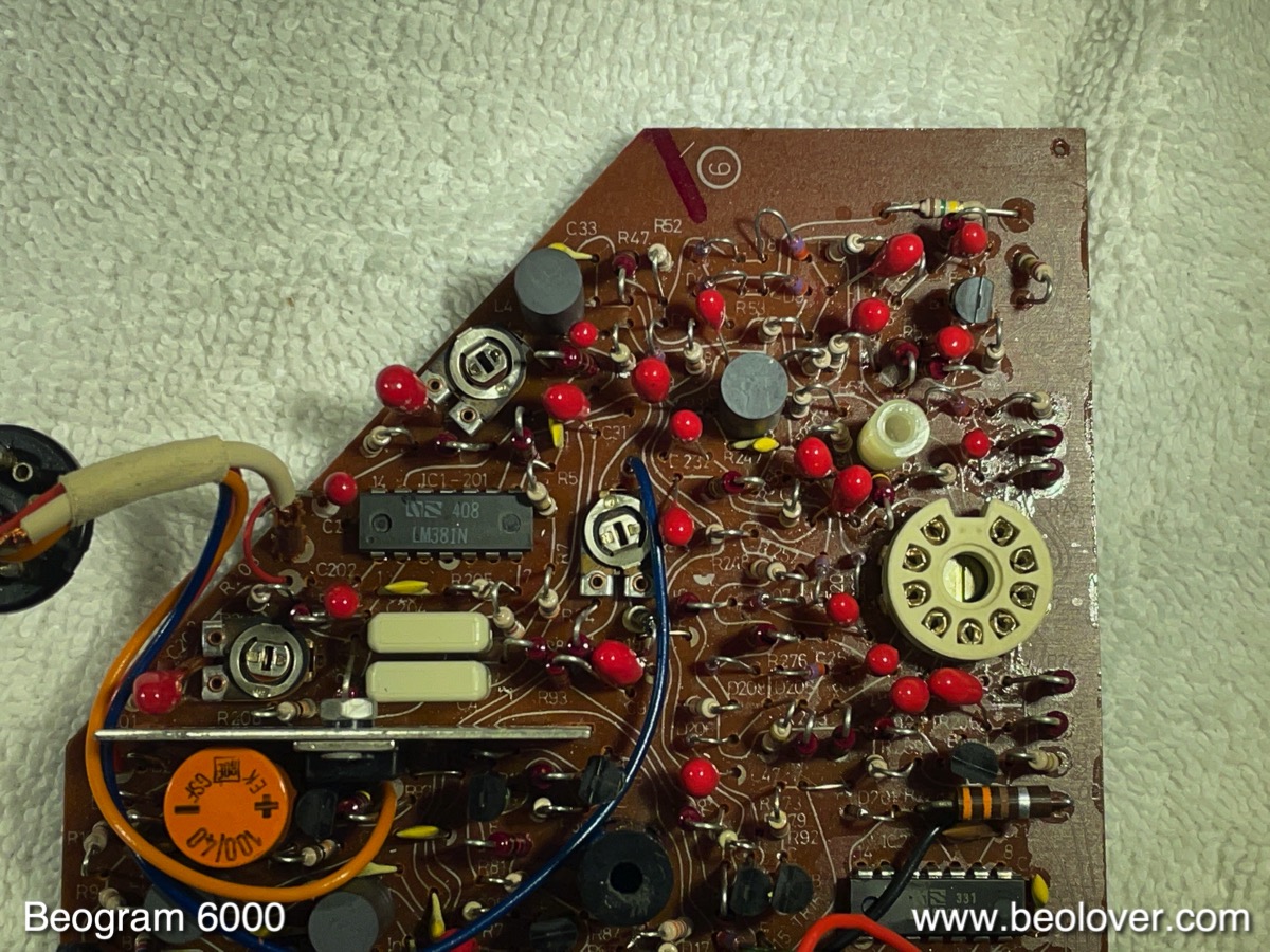
This shows the board after extraction:
And here the upper section after removing the piggy-backed smaller board:
I replaced all the electrolytic capacitors on the board. The ones in the 'stereo signal path' were replaced with fitting WIMA foil capacitors to reduce distortions:
Pretty! They know exactly why they package them in these pretty red little boxes!...;-)
I also replaced the CD 4 indicator lamp with a LED. If you use a high output LED that only needs a small current to light up, then you may want to add a ~3k resistor between the base of 6TR14 and GND to pull the base down sufficiently to turn the lamp off when there is no CD-4 signal/the switch is turned to OFF. I did that with a SMD resistor on the solder side of the board at a convenient location that could be bridged by the resistor. The blue resistor seen in the picture is the current limiting resistor for the LED to make it compatible with the 22.8V rail:
This shows the restored board
and the removed parts.
Quite a few electrolytic capacitors in this historic analog design! While in there I also added a switch in the back allowing connecting the output cable shield to the signal ground in case there is a hum issue:
This is where the other end of the switch connects at the output plug. I added it to the pin where the inner braid is connected:
This shows the board installed again:
After this I put the keypad back in place and did some listening. Unfortunately, I was able to hear some motor noise in the speakers when cranking up the volume with the arm down next to the platter.
Not too unexpected in a design like this since motors introduce a lot of noise on power rails, while the RIAA amp is very sensitive to small signals.
This was confirmed by a measurement with my Quant Asylum QA400 audio analyzer. The red trace shows the noise spectrum with the arm down after I put the Beogram back on the bench (note that this spectrum is shifted 20dBV higher to separate it from the blue spectrum that was measured after my fix was implemented). Most of these peaks, except the one at 60Hz come from the motor.
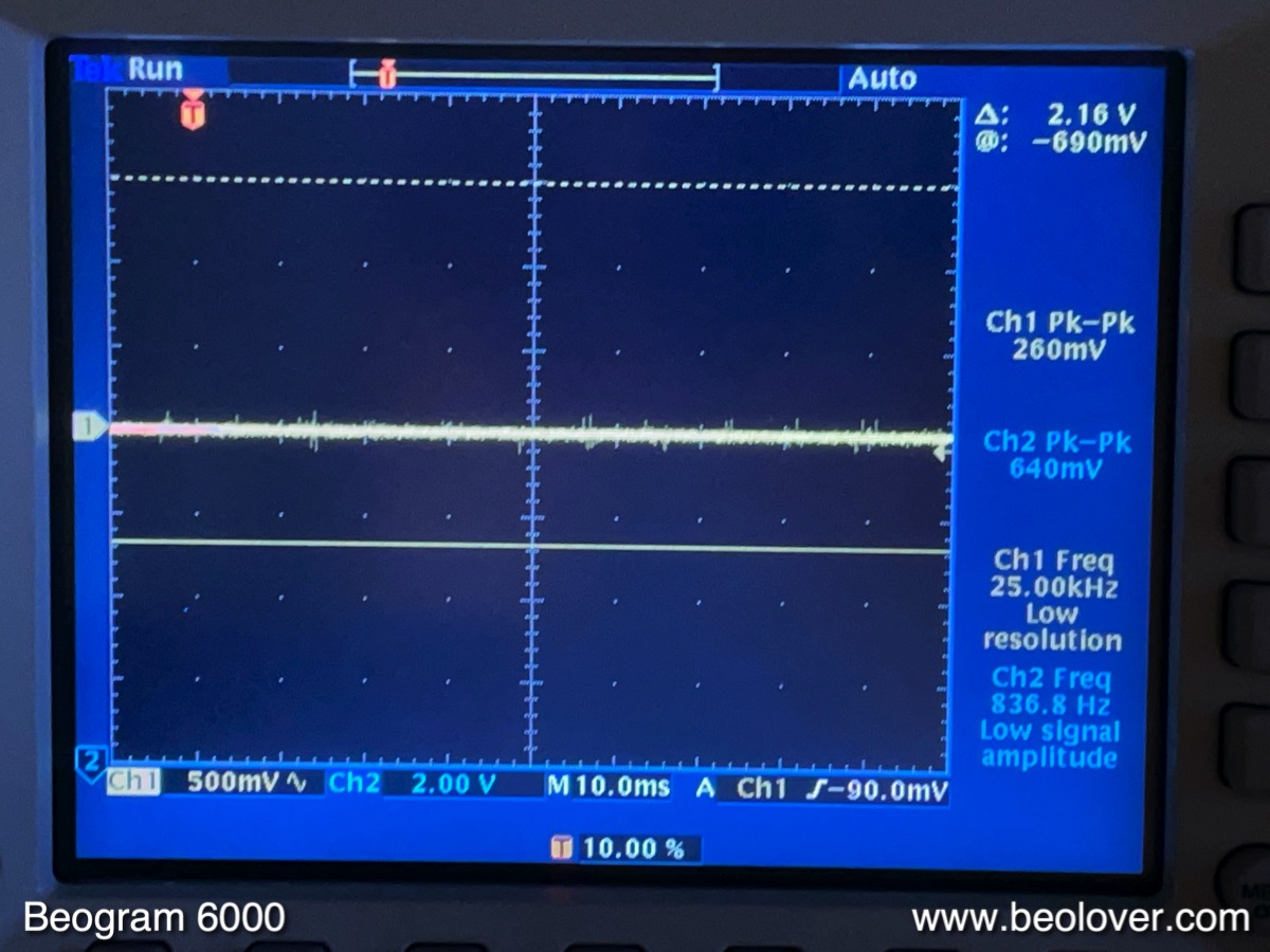
I hooked up the oscilloscope to the 30V rail (orange wires on 3300uF capacitors) and saw this (using AC coupling):
~500mV noise!
So I did two things:
First I converted the power supply of the CD-4 board from 'main PCB 22.8V rail referenced' to a 24V Zener reference. This is easy to do on this board. This shows the original power supply section of the board. The big capacitor is 6C94:
I removed this capacitor and implemented a 24V Zener diode in its place. In combination with 6R96 and 6R98 this created the classic Zener voltage divider to be fed into the base of an emitter-follower like 6TR17. One more thing had to be done to 'disconnect' the blue wire that is the 'reference' to the 22.8V rail of the main board. I did this by removing 6D20 while leaving the blue wire in place. This shows the section in its final configuration:
The second step I took was to implement a 'capacitance multiplier' in front of the two 3300uV reservoir capacitors:
Basically, at the positive terminals of the capacitors the orange wire from the emitter of 0TR1 feeds the regulated voltage to the capacitor. In the original configuration, a second orange wire then connects to the rest of the circuit. In my modification the orange wire now connects to the output of the capacitance multiplier and the input to the capacitors.
This is how the voltage looked after the added circuit:
Much nicer! And when I measured the noise spectrum, I got the blue trace in the above graph. You see that most peaks are gone. Only the usual 60Hz interference and a couple smaller peaks are left.
How does a 'capacitance multiplier' work? Essentially it is a bit of a misnomer, since it is rather an emitter follower that is referenced to a very low pass filtered (2k/100uF) low-current version of the original to be cleaned up voltage rail. Since the emitter follows the signal at the filter output, it removes all the high frequency stuff on the power rail. There is a
great Dave video on the EEVblog that explains all the ways to remove ripple and noise. I built it with a TIP102 Darlington to get a big gain, which allows to reduce the cutoff frequency even more since the current in the filter output can be very small while still being able to drive a large current to the load. This shows a simulation of my little circuit in iCircuit:
I assumed a 40V DC signal with a 1Vpp ripple on it (green) and a 1000x gain for the transistor, similar to a Darlington. The circuit cleaned this up to the yellow trace which has a 13mV ripple. So basically a two magnitudes improvement.
I listened to the deck again, and only a healthy RIAA pre-amp hiss came from the speakers when cranking up the amplifier with the arm down next to the platter! Beolovely!
My final act was to try measuring the total harmonic distortion (THD) and THD+noise (THD+N) of this RIAA amplifier using the QA400, which can calculate it from the FFT spectrum. THD numbers are always a bit ambiguous when reading manufacturer specifications since it is never stated under what conditions they were measured. So it may be difficult to directly compare my measurements with others. Therefore, I post the spectra that I measured along with the calculated numbers.
The QA400 outputs were connected with a BNC-to-minigrabber cable directly to the Left and Right Channel pins at the input plug of the CD-4 board. Then the deck was turned on at 33 RPM and the arm lowered to open up the signal path through the diode switch. The CD-4 switch was set to OFF.
I did two measurements for two input levels, -60dBV and -70dBV. These levels correspond to 14mVmax/10mVrms and 4.4mVmax/3.16mVrms respectively signals. I measured a few MMC cartridges a while back and they produced such levels during fairly loud passages.
The first graph shows the -60dBV curve. Right and left looked fairly similar, so I am only showing the right one for clarity. The signal strength of the amplified 1kHz tone is about -17dBV, i.e. we have an amplification at 1kHz of about 43 dBV. This gain resulted by setting the two gain trimmers in the opamp feedback to center position. For this spectrum the QA400 calculated THD=0.46% and THD+N=0.52%.
The second graph shows the same measurement at the lower -70dBV input level. It is obvious that the harmonics went down, and consequently the THD numbers are lower with THD=0.14. THD+N=0.8 is higher since the signal to noise ratio is now 10dB worse.
These THD values are considerably higher than what is stated for modern external RIAA pre-amps, which usually seem to be in the 0.0X% range at similar gains.
In my opinion this does not matter much since cartridges and the records themselves usually have much higher distortion levels, i.e. the small amounts added by this classic RIAA design will not matter much. I really like listening to this Beogram 6000. It sounds very nicely and gives you that awesome 1970s warmth that makes you think of bellbottoms and brown corduroy suits with wide lapels!...;-)