Featured Post

Beolover SyncDrive: DC Platter Motor Replacement for Beogram 4002 and 4004 (Type 551x and 552x)

Late Beogram 4002 and the 4004 (Types 551x and 552x), which have DC platter motors instead of the earlier synchronous AC motors usually suff...

Showing posts with label tantalum. Show all posts

Wednesday, May 9, 2018

Beogram 4002: Working the Main Board

On this project I am starting with the electrical restorations. The main circuit board is first. As usual I will replace electrolytic and tantalum capacitors that are 2.2uF and less with WIMA MKS capacitors. If there is room I sometimes replace 4.7uF capacitors as well. In this case the fit is too tight to install 4.7uF WIMA capacitors so I will stick with electrolytic replacements on those.

Here is the main board again as I received it.


Here is the speed select relay removed along with the speed trimmer resistors.


I am replacing the 45 RPM and 33 RPM speed control trim pots with sealed, multi-turn trimmers. For the speed selection relay I am using Beolover's custom RPM relay component. It is a sealed SMD relay mounted on a special adapter board so it is a direct replacement for the original relay (A Siemens relay in this case).


A key component on this board is the 1C10 capacitor. Beolover's exhaustive testing of the rebuilt DC platter motors has determined that the value of the 1C10 capacitor has a measurable bearing on the stability of the platter motor speed. In his testing of the DC platter motor from this Beogram unit he determined that a 10uF capacitor provides the most stable speed circuit. 


Here is the completed main board with its new parts.


Saturday, February 3, 2018

Beomaster 6000 (2702) restoration: recapping level amplifier with SQ decoder and pre-amplifier

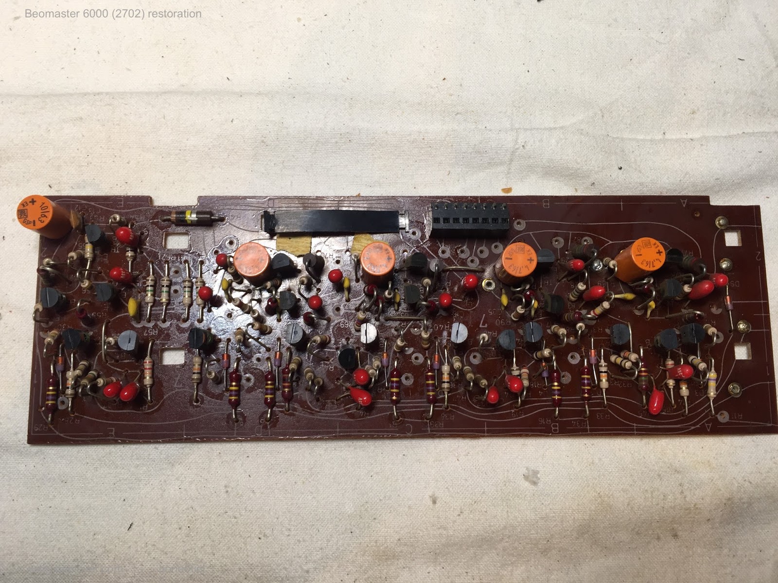
When restoring vintage audio equipment it is good practice to replace all electrolyte and tantalum capacitors. Today the level and pre-amplifier PCB's are done as well as the small PCB for the SQ decoder that plugs into the level amplifier. This was done to allow further upgrade to new quadrophonic (de)coding systems. There was no standard yet in the mid seventies and in fact there really never came a standard! During those days about a dozen systems existed. Some for records, some specific for tape: SQ, CD-4 (used in the Beogram 6000), QS, DY, EV, UD-4, Quad-8, Q4 (the very first - invented in the fifties), etc. None was really successful and all where abandoned a decade or so later.

Today we would probably call this quadro systems: 4.0 surround sound !

Anyhow, back to the recapping. When replacing capacitors it is obvious that the value and voltage rating is crucial and need to match. Sometimes two or more capacitors need to be combined (in series or parallel) to match the old one. It is common in speaker crossovers for example to see odd values that are no longer industry standard.

But dealing with recapping of PCB's in this Beomaster 6000 quad poses another challenge: box size ! On the pre and level amplifier there are more than 60 capacitors and mostly tantalum. They where chosen for the small size compared to the aluminium electrolytes for the same values (today electrolytes are a lot smaller than back in those days). But even today, when replacing those tiny tantalum's, it is often impossible to go for electrolytes because they simply don't fit in the space. The WIMA MKS foil capacitors are the best choice for me. But even then, one needs to be very careful what type is chosen. Don't go to high in max voltage rating, check the different box sizes between the different PCM measures (2,5 or 5mm distance between the leads). Some are square, some are rectangle. Many of the MKS (polyester film types) that I had in stock did not fit. 

This is for example the level amplifier before recapping


And after recapping


And the SQ decoder that fits in the black plug in the above PCB


The pre-amplifier was even more challenging


Only a few boards left now for recapping. But that is for a next post...

Monday, July 10, 2017

Beogram 4004 Type 5526: Starting the Restoration

Just like the Beogram 4002 turntable restoration I recently did, this Beogram has a bunch of debris inside from the disintegrated plastic transport bushings. Due to continuously finding pieces during the Beogram 4002 project I decided to start off with the debris cleanup on this Beogram 4004.


Every nook and cranny has some piece of debris in it.


Even the tangential arm assembly didn't escape the spread of the bushing debris.


Eventually I got everything cleaned up.


Next I decided to start in on the electrical restoration. The first thing is the power reservoir capacitor that mounts to the chassis. I am replacing the original 4000uF capacitor with a Beolover replacement that includes a 3D printed housing so it can mount with the capacitor mounting bracket.


The custom part makes this installation a breeze and professional.

Now for the Beogram 4004 main board. It has a lot of blue tantalum capacitors that need replacing and a few electrolytic capacitors I will also replace. For values 4.7uF and less I like using WIMA polyester capacitors. They are non-polar and last a long time. In a couple places where the larger 4.7uF WIMA capacitors don't fit, I will use Nichicon 4.7uF electrolytic capacitors.

This board will also get three trimmer resistors replaced: the 33 RPM adjustment trimmer, the 45 RPM adjustment trimmer and the calibration trimmer for the photo darlington adjustment. That is the sensor for the tangential arm transport position.

I will also replace the RPM speed select relay with a Beolover custom replacement relay module.

Here is the main board prior to the restoration work.


These next pictures show the new Beolover RPM relay and the trimmers that were replaced.


Here is the finished main board.


Next up is the small output board.

Saturday, September 26, 2015

Beogram 4002 (5513): Replacing the Electrolytic Capacitors

Today was recap day for the Beogram 4002 (5513) that I am currently restoring. I used my recently developed 3D adapter to replace the combined 4700/1000uF capacitor with modern, smaller 105C grade cans. Here are a few impressions.This is the original setup:

This is the 3D printed adapter with the new capacitors:
And a detail picture of the connections during the installation process:
And mounted in place. The 3D printed adapter fits into the original capacitor mounting clamp:
After the reservoir caps I also recapped the main board. This shows the original condition:
And after replacing all the Ta and Al electrolytic capacitors:
The sole capacitor on the output relay board will be exchanged once I take the keypad out to install a rebuilt replacement supplied by an expert beofriend in Denmark.


Tuesday, September 8, 2015

Beogram 4000: Replacing the Electrolytic Capacitors on the PCBs

While I worked on the breakout board needed to replace the RPM relay with a modern encapsulated signal relay, I also recapped the PCBs. I think it is worthwhile to replace these vintage electrolytic capacitors since the tantalum types can actually catch fire when they go, while the orange aluminum caps are often out of spec at this age. I usually use quality 105C grade capacitors from major Japanese manufacturers, good for another 40 years...;-)

Here are a few impressions:

This is the main board in original condition:

And here after replacing the capacitors (the RPM relay is still in there):

The power supply PCB also has two electrolytic capacitors. This shows the original board:
And here after the replacement:

All good now in the capacitor department! Here is a picture of the lovely old color coded tantalum capacitors. I wish they would make them still that colorful!
Ain't they pretty?? This is Beolove...;-). On to the reservoir caps.