Featured Post

Beolover SyncDrive: DC Platter Motor Replacement for Beogram 4002 and 4004 (Type 551x and 552x)

Late Beogram 4002 and the 4004 (Types 551x and 552x), which have DC platter motors instead of the earlier synchronous AC motors usually suff...

Showing posts with label spindle. Show all posts

Wednesday, July 2, 2025

Michigan Beogram 8002 Floating Chassis Components Restoration

I began the restoration of this Beogram 8002 turntable with the floating chassis components.

The main reason for that is two broken parts I discovered during the initial assessment.
I wanted to tackle those two (key) problems first because I wanted to make sure they could be properly fixed.

For the spindle nut with a broken guide wall for the bracket that connects it to the tangential arm assembly...I decided to go with a spare (or donor) spindle nut from my box of Beogram 800x turntable parts.


In the case of the broken tab that secures the Beogram 8002 position sensor assembly...I had to design a 3D printed part that would properly secure the broken tab and still allow the tab to let the sensor assembly board be removed.


It took some modification of my initial design but I finally achieved what I was after.
The 3D part glues onto the molded plastic that comes with the Beogram floating chassis.

The broken, plastic tab is also glued to the 3D part and the area of the chassis it broke off from.

The ends of the 3D part wrap around the chassis base on all four sides to provide strength.
The end closest to the servo motor has to have a slot for the sensor assembly.
The 3D part wall on the spindle side had to be made smaller than I originally designed it to leave room for the sensor wheel and to attach/remove a rubber belt.

Here is another view.


While I had the floating chassis components where they are still easily accessible, I decided to perform a few Beogram 8002 adjustments that involve the tangential arm assembly.

To do this I removed the spindle assembly and just left the arm assembly on the two rails.


This allowed me to manually slide the tangential arm assembly wherever I wanted to without manually rotating the spindle (which gets old fast).  I also didn't want to wait until the electronics were completed and working...then take the arm assembly out again.

With this setup I adjusted the height of the fixed-arm (sensor arm) relative to the top of the platter.
The distance per the service manual is 19.5 mm (different than the Beogram 8000 and Beogram 400x turntables).

That adjustment screw is shown in blue text in the above photo.


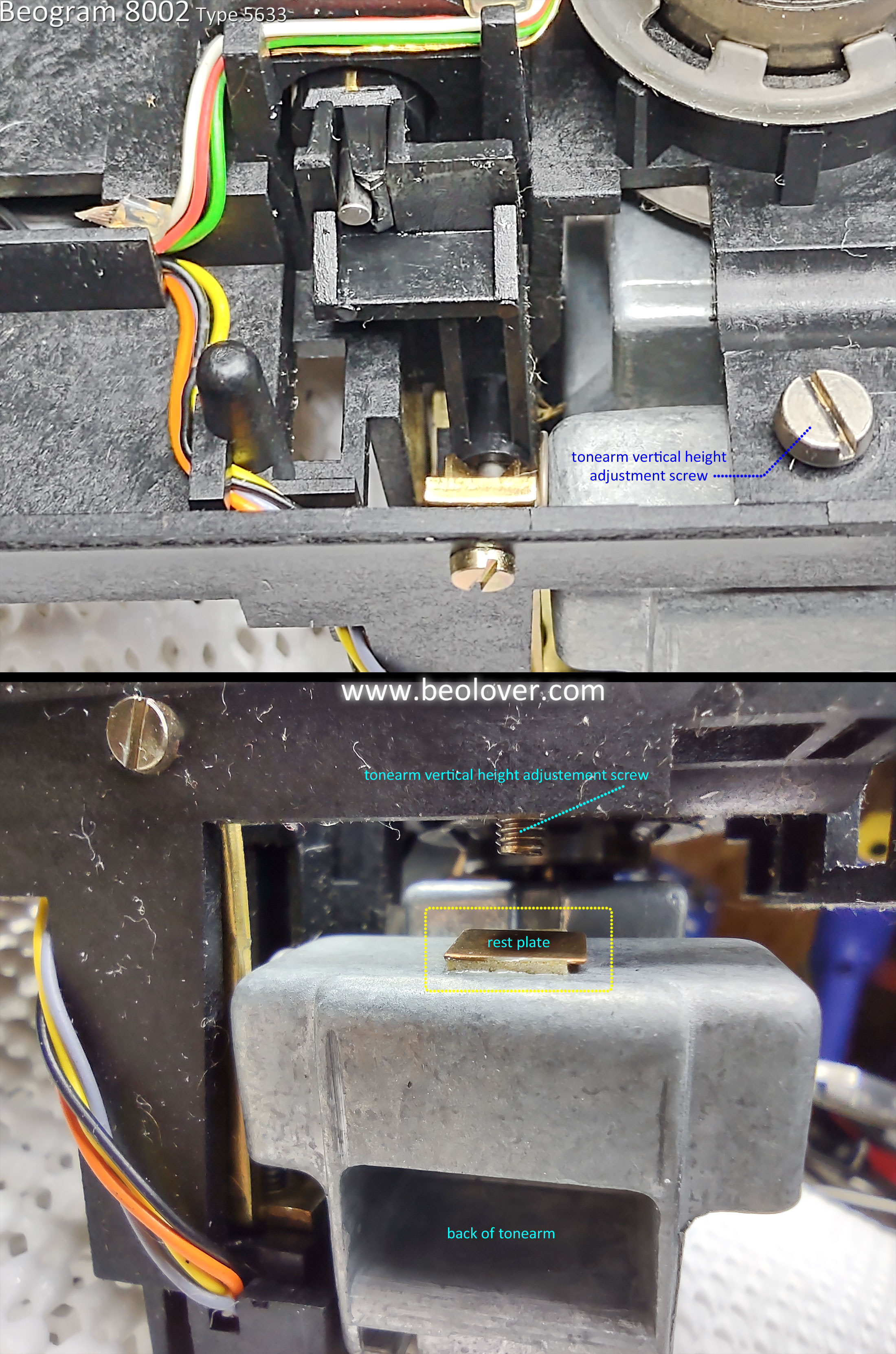
With the fixed-arm height set per the service manual the next adjustment is to make the top of the tonearm match the top of the fixed-arm.

The adjustment screw for the tonearm height is underneath the tangential arm assembly so you can see why I want to get it out of the way first and not come back to it.


I am not showing the phono cartridge tracking force calibration here but I did do an initial calibration of the tracking force counter-weight, phono cartridge and force selection slider while I had the floating chassis components apart.  I will do a final check later when the Beogram is assembled for testing.

Next, I cleaned and applied rubber cleaner/treatment to the two damping rubber inserts on the rear tangential arm rail. 

Note that the rubber dampers are only on the rear rails of Beogram 8002 turntables used with 60 Hz line voltages.  They aren't necessary where the line voltage is 50 Hz.


The last floating chassis component tasks I worked was to replace the audio muting relay and the two capacitors on the +5 VDC regulator.

Here is the muting relay replacement.
Note that the Beogram 8000 has a different muting relay.


Here are the only two floating chassis mounted electrolytic capacitors that get replaced.


The next post for this Beogram 8002 project will focus on the main electronics restoration work.

Wednesday, October 30, 2024

Beogram 4002 (5513): Another Beogram From Houston - Mechanical Work

The restoration work on this Beogram 4002 (Type 5513) begins with the various mechanical restoration tasks.

Those include cleaning out the debris from the cabinet base and some disassembly of the floating chassis components for cleaning and lubricating.

The arm lowering & raising lever is attached to the fixed arm.  The pivot for that lever can occasionally get gunked up so we typically remove it for a clean and lubrication.


The arm lowering damper is also cleaned.  The rubber washer on the end of the plunger gets replaced with a new washer and the metal part of the plunger is lightly lubricated with a silicone lubricant.


The tangential arm spindle parts are removed for cleaning and lubrication.
I don't immediately re-install the spindle however as I find it easier to make a few Service Manual mechanical adjustments with the tangential arm assembly free to slide back and forth.


Before making any Service Manual mechanical adjustments I like to move the four set screws that sit underneath the two metal rails the tangential arm assembly rides on.

These set screws are for adjusting the height of the rails but the slotted end to make the adjustment with sits underneath the floating chassis.  I remove them and re-insert them from the top.  This allows any change in their height to be made from the top side of the floating chassis without having to remove the floating chassis from the cabinet.

Here is a photo of one of the re-inserted set screws.


That gives a little peace of mind in case some change in the tangential arm assembly height is necessary.  Normally it shouldn't be but the set screws allow about 3 mm of height adjustment.

Next I reassembly the tangential arm assembly and go through the adjustments to make sure the arms are perpendicular to the back rail, parallel to each other and have the proper distance to the platter.

The Service Manual says the distance between the Fixed arm and Tonearm is 7.7 mm.


The top of the Fixed arm to the top of the platter (metal) surface has to be 23 mm.


After that is set the tops of the two arms (Fixed and Tonearm) should be even.  If they are not, the Tonearm height can be adjusted. 


With a phono cartridge mounted I check that the Tonearm and cartridge vertical alignment (azimuth) is good.


I set the Tonearm lowering limit so the stylus of the cartridge is about 0.5 mm above the lower platter rib.


I calibrated the tracking force of the Tonearm/Cartridge so that it measures 1.0 gram with the tracking force knob set at 1 gram. 


After that calibration I set the tracking force knob to 1.2 grams.

Before installing the Beolover Tracking Sensor Lamp component to the Beogram 4002 Tracking Sensor Assembly, I checked and adjusted the metal aperture so it is 1 mm above the Tracking Sensor.


The Beolover Tracking Sensor Lamp was then installed followed by the Tangential Arm Assembly spindle parts.  The plastic pulley on the spindle was replaced with an aluminum pulley.
When the spindle was installed I lubricated it with a mixture of grease and oil.  Not too thick and not too thin.


The floating chassis components can now be re-installed in the Beogram 4002 cabinet base where the suspension will be adjusted so the top of the platter is even with the cabinet aluminum deck.

Along with that, the platter motor and reservoir capacitor assemblies will be installed.


I'm pleased with the mechanical adjustments so far.  The re-installed floating chassis aligns good with the aluminum deck plate so it is on to the rest of the electronic restoration tasks.

Those include the restoration work on the main PCB, the output (audio muting) PCB, the LED lamps for the speed indicators, the arm detector lamp (in the Fixed arm) and the contact cleaning on the Beogram control panel buttons...Plus all of the related adjustments.

Monday, January 23, 2023

Beogram 8002 Type 5633: Floating Chassis Restoration Tasks

I wrapped up the work on the Beogram 8002 floating chassis. It should be ready for some functional testing of the turntable operations in the next blog post.

Here is the floating chassis before starting the restoration work on it.


It has a bit of dust as you would expect but nothing major to clean up or repair.

I removed the center hub to inspect the tachodisc and speed sensor.


Next is the disassembly of the tangential arm assembly for inspection, cleaning and lubricating.
I will also check the arm raise/lower solenoid and mechanical parts. 


The arm lower/raise mechanics looked good.
While the arm assembly was turned over I took the opportunity to align the tonearm height with the sensor arm.

Interestingly this Beogram 8002 unit has a little, square rest plate for the tonearm height adjustment screw.  Usually there isn't anything there to keep the screw from contacting the metal back of the tonearm.  That can cause problems with the arm lowering operation so I often have to place a small piece of Dura-Lar plastic there.  In this case, the problem is already taken care of.


Now it is time to clean the old oil and grease from the spindle, rails and attachment pieces.
Then re-lubricate everything and reassembly the arm assembly.


Because this Beogram 8002 was configured for the North America market the rear guide rail has rubber tip ends to dampen any vibrations from the 60 Hz line voltage.

I applied some rubber restoring fluid to the rubber ends when I reassembled the arm assembly.
For re-lubrication of the spindle I still use the original B&O combination of Rocol MTS 1000/2000  with Mobil NUTO H32 mixture. However, a good modern, synthetic oil will also work fine.  Just don't over lubricate the spindle where oil flies off when the spindle spins.  
On the shiny guide rails I apply either some M-kote DX Paste Grease or some Tri Flow Dry Lube.
At the pivot points of the spindle where it attaches to the chassis I use a little bit of Tri Flow Red Grease.


Here is the tangential arm assembly put back together with the tonearm aligned with the sensor arm.


There were a couple of electrical restoration tasks left to do that I didn't complete on the previous post.

One is the replacement of the phono muting relay.
I replaced the original muting relay with one I sourced from Beoparts.


I also installed my usual test connector for adjusting the LDR sensors that are used for the forward and reverse arm scanning operation.  It is kind of a pain to connect DMM probes to make the voltage measurement while adjusting the sensor aperture so I install a three wire test connector that allows checking (and adjusting) the LDRs without opening the Beogram 8002 into its service position.


The Beogram 8002 turntable components can now be assembled and tested.

Saturday, July 31, 2021

Beogram 8002 From North Texas: Testing the restoration work so far

This Beogram 8002 is ready to do some testing of the restored components before starting in on the service manual adjustments.

The recapping of the circuit board, transformer and chassis capacitors was completed in the previous post
There aren't any capacitors in the button control panel but there are two LDR devices plus a lamp that will need to be adjusted during the service manual checks. On rare occasions those LDR devices and the lamp require replacement but I usually leave them alone. However, I do like to install a small test connector that is handy to use in testing the functionality of those two LDR devices.

Here is the Beogram 8002 button control panel removed and looking at the underside.
The photo shows the two adjustment screws for the LDR devices. Unfortunately there are not easily accessible test points for measuring the LDR voltages while doing the adjustment.


There is a small set screw and plastic tabs that keep the circuit board in place on the panel. You have to be careful in removing the board as I have come across quite a few panels where the plastic tabs are broken off...likely by someone that didn't know what they were doing.


Turning the circuit board over I noticed that the chassis ground connection was loose.


I cleaned off the copper area and resoldered the wire.


The LDR adjustment calls for measuring the two LDR devices (reverse and forward) to ground so I will add a small 3-pin connector with those signals.


The test connector is a female connector so there are no exposed pins to short out when the test connector is not being used. When I make the LDR service manual adjustment I will insert a 3-pin male plug for my testing.


I also plan on measuring the various Beogram 8002 sensors with an oscilloscope so I soldered on some temporary test wires for those signals on the back of the main PCB.


That takes care of what I will need for electrical measurements while testing the Beogram.
Now I just need to reassemble the tonearm assembly in the floating chassis.

I had removed the tonearm assembly for cleaning and lubricating the Beogram.  
I cleaned off all of the old lubricants and am ready to apply new lubricants to the Beogram 8002 spindle and tangential arm assembly rails.


You will notice that the rear rail is longer than the front rail and has a rubber sleeve (with a metal end cap) on each end. This type of rear rail is only on Beogram 8002 models that were built for markets where the AC line is 60 Hz. Bang & Olufsen engineers determined that the 60 Hz models were susceptible to some vibration that needed damping.  This is a USA model Beogram 8002 so it has the rear rail built with the damper. Because these turntables are over 30 years old I always clean and put some rubber conditioner on the ends.


To lubricate these parts I use some Tri-Flow synthetic grease on the mounting points of the spindle followed by a mixture of Rocol MTS 2000 and ESSO NUTO HP32 (1:1 ratio) on the spindle itself. On the front and rear rails that the tonearm assembly slides on I use some Tri-Flow dry lube. I have also used white D.C. M-kote paste on the rails as I use on the Beogram 400x turntables.


While the tonearm assembly is removed from the spindle and rails there is one service manual check/adjustment to go ahead and make.

The horizontal parallelism adjustment screw is on the bottom of the tangential arm assembly. So it is not accessible when the arm assembly is installed.  

This adjustment is to line up the top surfaces of the tonearm and the fixed arm so they are even with each other. Here is a photo of the adjustment screw.


Another adjustment screw that is only accessible from underneath the tonearm is the screw that holds the tracking force slider control in place. Sometimes this screw can become loose and the tracking force slider slides too easily. Often drifting away from the setting an owner sets it to. 

While I have easy access to the screw I made sure it is securely in place and the slider does not move too easily (there should be a little bit of friction).


Reinstalling the rails, spindle, spindle nut and tonearm assembly requires a bit of maneuvering of the parts all at once but it isn't too difficult. The rear rail must be fit through the tonearm assembly base and through the bracket that attaches to the spindle nut. Obviously the orientation of the parts are critical as well.


Everything can now, gently be tilted over to fit properly on the floating chassis.


The tangential arm servo motor belt and the position, rotary sensor assembly can now be reinstalled.


I can now start connecting floating chassis components together to see how the restored parts work.

A couple of quick checks are needed though.
Check that the center hub of the Beogram 8002 (with the tachodisk for the platter speed detection) spins easily and does not contact any part of the sensor assembly.  This one is good.


The top platter is not necessary for testing the basic Beogram 8002 functionality but the black, sub-platter is. The metal sub-platter passes between the curved slot of the two tangential drive motor components and is actually part of the motor. Without the sub-platter in place nothing will turn and the Beogram 8002 will try to drive the motor anyway ... and could blow a fuse.


Finally...here we go with the first power on test of the restored parts.
Everything that needs to be connected is connected.


You can see that the Standby dot is illuminated and ready to go.


Pressing play I get an operating platter, the tonearm assembly moves and the Beogram 8002 control logic is able to lock in the platter speeds.


As I expect to observe (and hear) the Beogram 8002 platter and tangential arm assembly operate extremely quiet and very smoothly.

That is it for this post. 
Next time I will measure the power supply voltages and view some sensor signals on the oscilloscope.
I will also finish up the service manual adjustments for the tonearm tracking force, record tracking and the forward/reverse LDR scanning voltages.