Moving on to the electrical tasks on this Beogram 8002 project...
There are electrolytic capacitors in the Beogram 8002 in four locations: the floating chassis, PCB 1, PCB 2 and inside the transformer box. Typically not all of them will be out of tolerance but it is a good move to replace all of them rather than wait for them to fail one at a time.
I will start by showing the replacement of the two capacitors on the floating chassis.
These two, 0C1 and 0C2, are part of the Beogarm 8002 +5 VDC regulating circuit.
The two capacitors are easy to get to although the yellow, black and blue wires should be disconnected and moved out of the way first.
On this project the Beogram 8002's owner had already purchased a capacitor kit for it. The kit contains most of the capacitors I normally replace and they are good quality capacitors so I will use them.
Here are the new new 0C1 and 0C2 capacitors installed.
PCB 1 is the main board of the Beogram 8002 while PCB 2 piggybacks on top and inside a shielded, metal box.
PCB 2 houses the Beogram 8002 microcomputer IC and has just one electrolytic capacitor to replace.
It is a difficult one to deal with though. The negative lead side is soldered to both the top and bottom layers of the board. In addition, the space is a very tight fit and is right next to the microcomputer IC.
This lone electrolytic capacitor, 2C28, is for the +5 VDC supply voltage to the microcomputer IC...so pretty important :-).
I like to cut the exposed leads on the 2C28 capacitor to remove it first, then desolder and remove the remaining parts of the lead once I have more room.
This photo shows the other side of PCB 2 and the other two solder points of 2C28.
A number of years ago we started replacing the 40-pin IC socket for the microcomputer device on these Beogram 8000/8002 restorations. Removing the old IC socket provides more operating room and the new 40-pin socket with tulip style contacts is a sturdier part than the original socket. It provides some extra insurance in reliability and is easy to replace during this capacitor replacement task.
The new 2C28 capacitor is in place and so is the new 40-pin IC socket.
I re-inserted the microcomputer IC (while taking electrostatic precautions of course).
I will apply new thermal paste to the top of the microcomputer IC later when I re-install the metal lid that has the heatsink for it.
One other step I performed on PCB 2 was to use a soldering tool to reflow the solder joints on all of the board connectors. We have found that those connector-board solder connections can become faulty over time and they are not something a visual inspection can always catch. It is safer to just reflow the solder.
In case any Beogram 8000 owners are wondering, the microcomputer IC in the Beogram 8002 and Beogram 8000 are not compatible. The PCB 2 board and housing look the same but the functionality of the microcomputer IC itself is different enough where they are not interchangeable.
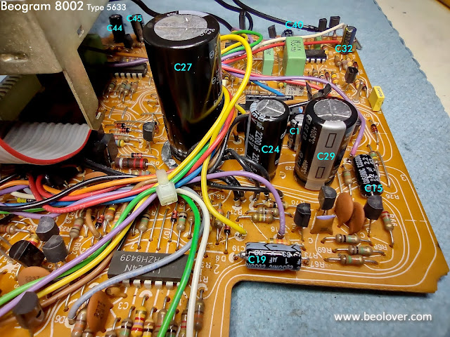
I used this photo above but I will include it again. The photo shows all of the PCB 1 electrolytic capacitors that will get replaced except for the one hidden underneath the metal shield box. I will show that replacement capacitor a little later on.
As I said earlier, not every electrolytic capacitor in the Beogram 8002 will be out of tolerance but there are always some that are...
Both of those capacitors are part of the Beogram 8002 power supply circuitry.
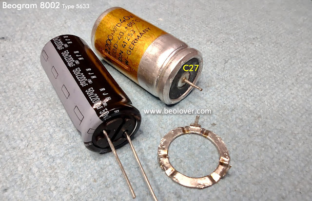
The largest capacitor, 1C27, which is for +15 VDC supply filtering was still in tolerance but it is being replaced now while all the other work is being performed.
1C27 is a little unusual in that it has a three prong base for its negative lead. The three prongs are for mechanical support and I have never found a modern replacement for this type of packaging.
The new capacitor is the common, two-lead, through-hole style of capacitor.
The Beogram 8002 PCB 1 board expects the 1C27 capacitor base to connect two of the board ground connections via that three prong base. That can be accomplished with a jumper wire on the trace side of the PCB 1 or I can pop off the three prong base from the original 1C27 capacitor and re-use it.
I like to opt for the second option.
The new 1C27 capacitor positive lead goes right in the center of the three-prong mounting ring.
The negative lead gets bent around the mounting ring and soldered to it.
The new 1C27 capacitor will fit into the original PCB 1 holes and soldered in place the way the original was.
Here is that PCB 1, C28 capacitor that is underneath the PCB 2 shield box.
On PCB 1 on the other side of the shield box is 1C4.
That accounts for all of the PCB 1 electrolytic capacitors.
The last electrolytic capacitor, 4C1, is a non-polarized capacitor located inside the transformer box.
The modern replacement capacitor is much smaller in its physical size so we created a 3D printed mount for it.
While I have the soldering tools out I took the opportunity to replace the audio muting relay on the Beogram 8002 output board, the small board that the 7-pin DIN connector is mounted to.
This is another precautionary change. We have seen enough of these relays start to fail where it is safer just to replace them rather than wait for them to fail.
Here are the before photos.
Here is the new Omron relay installed.
In the next post I will lubricate and re-install the tonearm assembly.


No comments:
Post a Comment
Comments and suggestions are welcome!