In wrapping up the Beogram 8002 floating arm assembly and electronic control restoration work I took some time to measure the activity of the Beogram 8002 servo motor and its control signals.
To get to that point on this Beogram project I had to adjust the tracking force of the phono cartridge and set the sensitivity of the tracking sensor.
Those tasks are performed with the Beogram 8002 plugged in and able to operate but with the platter motor disabled. The way that is done is to disconnect the Beogram 8002 P4 connector from PCB 1 (with the Beogram unplugged as well of course).

The arm assembly can now operate and be lowered onto the disabled platter to measure and adjust the tracking force of the tonearm.
This is done with an MMC cartridge installed on the tonearm and a scale to measure the tracking force.
I use a digital scale as shown in the next photo.
My method of setting the tonearm counterweight is to set the tracking force knob to 1 gram on the slider indicator, then adjust the counterweight adjustment screw so the digital scale measures 1 gram with the arm lowered.

The tracking sensitivity is performed by placing a test record on the platter, moving the arm over the record and lowering the arm on a track in the center of the vinyl record. The platter is then manually rotated as you observe the movement of the Beogram servo motor drive belt. The pulley and motor should move (to advance the arm) within 1 revolution of the platter. After that you should see the arm advance in varying small increments depending on the characteristics of the track. The tracking control should be keeping the arm tangential to the record.
Here is the adjustment screw for the tracking sensitivity.

Also shown in the photo is the SO (Switch Off) switch. The SO switch turns off the servo motor when the arm assembly returns to the Standby position and the SO switch enables the arm position counter during Play. The SO switch can be moved slightly with its adjustment screw to manipulate the actual setdown position of the stylus on a record.

This section from the Beogram 8002 schematic shows the servo motor and its control signals.

The diagram shows the signals from the Forward and Reverse scan LDR controls feeding into the servo motor drive control amplifiers (1IC2). That is why it is important to set the steady-state voltages on the scanning LDR devices. This is where I use my little test connector that I added to the Beogram 8002 control panel board. Here is a photo of the forward and reverse scanning LDR devices after I adjusted their voltages.

The LDR voltages (when Play is pressed and the tonearm is paused) should be set to 620 mV according to the service manual. A value from 620 mV to 700 mV is actually okay. I usually aim for 620 mV to 650 mV.
The Beogram 8002 servo motor belt is important to get right. It should not be too tight or it will damage the servo motor over time and the tangential arm assembly control will not operate correctly.
Here is a photo of the servo motor belt.

I have discovered that these servo motors (DC motor) can sometimes start squealing as they age.
It is possible to add a little synthetic turntable oil to the shaft of the servo motor (not on the pulley of course).
That turned out to be the case with this Beogram 8002. The pulley started making quite a racket the more I ran tests on the turntable where the arm had to move.
Once I applied a drop of oil and changed the servo motor belt, the operation returned to normal.
For monitoring the operation of the servo motor during record play I selected the arm LIFT command, one of the arm position sensors, the forward servo drive command at the amplifier input and the actual servo drive signal at the motor.
Here is a photo of the measurement points.
It is possible to add a little synthetic turntable oil to the shaft of the servo motor (not on the pulley of course).
That turned out to be the case with this Beogram 8002. The pulley started making quite a racket the more I ran tests on the turntable where the arm had to move.
Once I applied a drop of oil and changed the servo motor belt, the operation returned to normal.
For monitoring the operation of the servo motor during record play I selected the arm LIFT command, one of the arm position sensors, the forward servo drive command at the amplifier input and the actual servo drive signal at the motor.
Here is a photo of the measurement points.

With these four measurement points I could view the servo motor as it goes from Standby mode to record play.
That sequence results in the Beogram 8002 driving the servo motor at fast speed when the Play button is pressed until the arm reaches the setdown point. At that point the servo motor slows down and stops at the setdown position. The LIFT command is energized and the arm lowers onto the record.
The setdown point should be on the record lead-in groove and that will result in the servo motor driving the arm through the lead-in groove and stopping at the first record groove with music content.
Now the tracking control will advance the servo motor as the phono stylus moves along the record groove. That path moves the tonearm inward towards the platter spindle.
The movement of the arm will trigger the servo motor to advance the arm assembly so it remains tangent to the record. That controlled movement is dependent on the tracking sensitivity adjustment procedure performed earlier.
Here are the oscilloscope screen captures.
That sequence results in the Beogram 8002 driving the servo motor at fast speed when the Play button is pressed until the arm reaches the setdown point. At that point the servo motor slows down and stops at the setdown position. The LIFT command is energized and the arm lowers onto the record.
The setdown point should be on the record lead-in groove and that will result in the servo motor driving the arm through the lead-in groove and stopping at the first record groove with music content.
Now the tracking control will advance the servo motor as the phono stylus moves along the record groove. That path moves the tonearm inward towards the platter spindle.
The movement of the arm will trigger the servo motor to advance the arm assembly so it remains tangent to the record. That controlled movement is dependent on the tracking sensitivity adjustment procedure performed earlier.
Here are the oscilloscope screen captures.

Here is a measurement that captures the Press Play event through to tracking the first record groove.
Notice that at the point the record is being played that the little "humps" in the Servo Motor signal (at P1-1) are when the motor is advancing the arm a bit. Also note that the position sensors do not register a pulse for every motor advancement. That is because the pulses on the position sensors occur when the sensor lamp hits the sensor between the openings in the sensor wheel. As can be seen on the 2IC1-28 sensor in the photo, there are times when the motor is advancing but the sensor signal is quiet. The sensor wheel is blocking the light during that time and the motor is only slightly advancing the wheel.


One more service manual adjustment to mention is the distance from the platter surface to the top of the sensor arm. That distance should be adjusted so you get 19.5 mm from the platter surface to the top of the sensor arm. There is a screw at the top of the sensor arm for that adjustment.

This adjustment is to set the distance of the phono cartridge stylus at a safe distance from the surface of a record. It is easiest to perform this when the floating chassis assembly is apart. The reason for that is while setting the end of the sensor arm position is easy from the top of the arm, the corresponding adjustment of the tonearm height is made underneath the tangential arm assembly. That means pulling up the tangential arm assembly from the guide rails and spindle again.
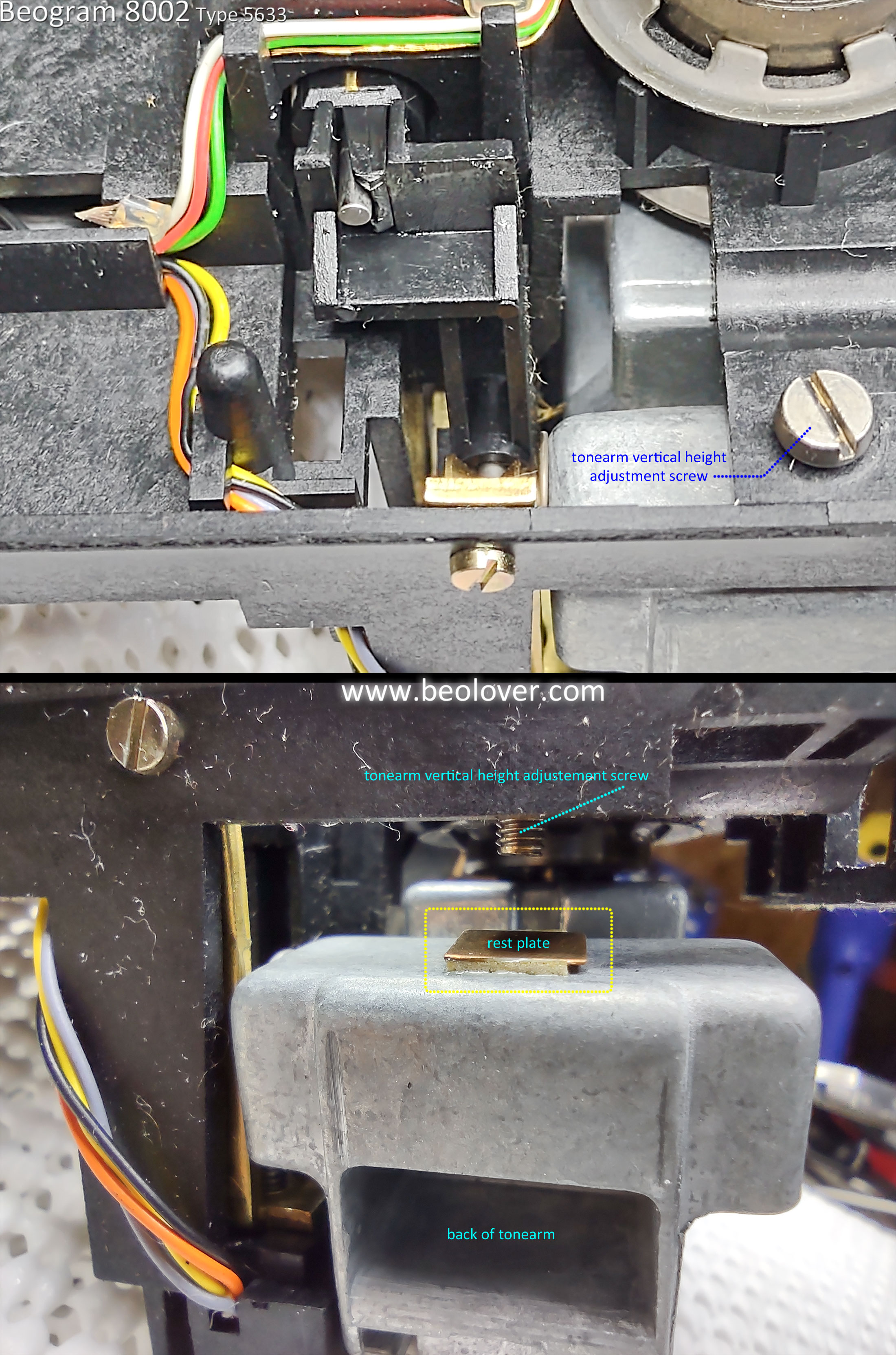
As I said, the result of this adjustment is so the end of the tonearm is where the stylus can safely scan over a record with good clearance. This adjustment has nothing to do with the Vertical Tracking Angle of the phono stylus. On a Beogram 8002, the Vertical Tracking Angle is fixed and cannot be adjusted.

All of the floating chassis and sensor adjustments are complete on this Beogram now.
The completed floating chassis assembly can play a record all the way through and I can test the record play by connecting up these Beogram 8002 components to my Workshop Beomaster 8000.
While I am testing the record play I can start in on the Beogram 8002 cabinet restoration tasks.


