Featured Post

Beolover SyncDrive: DC Platter Motor Replacement for Beogram 4002 and 4004 (Type 551x and 552x)

Late Beogram 4002 and the 4004 (Types 551x and 552x), which have DC platter motors instead of the earlier synchronous AC motors usually suff...

Showing posts with label 1651SMBG4002. Show all posts

Thursday, January 8, 2026

Beogram 4002: Installation of a New Dust Cover and Aluminum Trim

I recently received the back of a Beogram 4002 dustcover from a customer in California for the installation of a new dust cover and aluminum trim (Beolover now offers this as a standard service). This shows the received parts on the bench:

My customer already had the hinges removed. This made it easy to check if they were not bent using a special tool that I made a while back when a new hood cracked due to bent hinges (they caused it to chafe on the metal back, and after a while it simply cracked off the hinges due to the stress that occurred every time it was opened or closed). In this case the hinges were perfectly 'spec':
I re-installed them on the black back part. This one was an earlier design that still had the nice set screws for the dowel pins that hold the hinges in place. The set screws are located under separate screws that cover the threads for the set screws:
After removing the screw the set screw can be screwed out. This shows it all the way out for clarity:
Normally, they only need to be loosened a turn or so and then the dowle pin can be stuck in from the side. This shows one of the hinges installed
and here the other:
This shows the components before putting them together: DKsoundparts hood, Beolover aluminum trim and the original hinge:
I strongly recommend doing a quick test with a new hood if it really works with the assembled dustcover back. The new DKsoundparts hoods are a bit 'tighter' than the original ones and the metal back gets closer to the plexiglass than an original one would. Therefore, it is crucial to make sure that there is no chafing. If there is the plexiglass will likely crack after a while. So I now always bolt the metal part in for a quick check if there is any contact between metal and plexiglass:
Once the parts are bolted together, I manually crank the hinge and watch closely if there is any issue. If there is interference, it will most likely be close to the sides. This shows the right hinge in the position with closest metal to plexiglass proximity. A satisfying ~1mm gap can be observed:
And there the other side with a similar gap:
This was no surprise since both of the hinges had passed by calibration tool at the beginning of my process. 
Sadly, later Beogram 4002/4004 do not have the set screws for the dowel pins anymore. Their pins are pressed in and in many instances they cannot be removed without the risk of damaging the black metal back. In such cases the only remedy when the hinges are bent enough to cause interference is Dremeling the plexiglass a bit until friction-free operation is achieved. Luckily, the 'region' that usually needs to be Dremeled is not visible during normal use of the turntable, i.e. this can be done without harming the appearance of the unit.

On to the installation!

I removed the hinge part and installed small 'filling pieces' in the channels that they designed in the back of the hoods where the aluminum trim needs to be installed. Not sure why there are these channels, maybe a requirement for the casting process. The original hoods do not have it. These channels are a bit annoying in that they make it difficult bending the aluminum trim smoothly. There is nothing under the trim when it gets bent, and so the bend is less 'sharp' in the area of the channels. These little 3D printed pieces try alleviating this issue. I epoxy them into place and then trim them with a razor blade:
The next step was determining the perfect center position of the aluminum trim. I do this with my alignment tools that clip to the hood. They make it very easy centering the trim:
Once the trim was centered I made a pencil mark across the trim and a piece of blue tape on the hood:


Then it was time to bold the back part in again. I usually put a bit of white carpenter glue on the threads in the hinges:
The idea is to hold the screws firmly in place since they cannot be bolted in very tightly. If they are bolted in too hard, the hood can crack again after a while. The white glue is soft enough that the screws can still be removed if need be, but it will hold them in place against vibrations etc...
Then it was time to glue the aluminum trim on and bend the side pieces. I use a specially designed bending block. It makes it easier to get a good bend around the corner:
The final step was inserting the hood bumpers on the front corners:
These bumpers come with the DKsoundparts hoods. And here a picture of the final result!
Beolovely! This hood assembly is ready to be returned to its Beogram 4002!


Thursday, April 10, 2025

Beogram 4002 (5503): Intermittent Tracking, Installation of New Carriage Motor and Restored Keypad and Update to Latest Beolover State-of-the-Art

I recently received a Beogram 4002 (5503) that I had restored in early 2020. After running for a while it came back in August 2023 with a fried H-Bridge. The H-Bridge is responsible for driving the DC carriage motor. It allows reversing the current direction even if there is only a single positive voltage rail in the system. It does that with transistors that act as switches to reverse the polarity on the motor leads. These transistors need to be able handling the motor current. If everything goes well, the current capacity of the transistors is safely above the current drawn by the motor in all operational situations.

Electric motors draw more current when they run under load since they run slower at the same applied voltage. The slower RPM causes the motor back-EMF (the self-induced voltage in the motor, which is opposed to the driving voltage) to be lower, so more of the applied voltage arrives at the motor coils, which in turn increases the current in the motor windings. This is a great feature of electrical motors since it means maximum torque at zero RPM, great for burning some rubber at a green light to impress ICE vehicle drivers (whose torque-to-RPM ratio is reverse: Minimum torque when the car is at rest and maximum torque when it is at speed...;-).

But this also means that if a mechanical system that is driven by an electrical motor develops more friction over time due to hardened lubricants or dry motor bearings, the motor will draw more current than when the system was new.

I finally came to realize over the years that this may be the root cause for H-bridge failures in Beogram 400x. The H-bridge transistors are able to handle currents of 1 Amp max. And when everything is according to spec fast forward or reverse typically draws about 0.1-0.2 Amps. 5x is a decent safety margin. But when there is additional friction, the current can get dangerously close to 1 Amp or even exceed it. This is evident from the often found blackened PCB surfaces under failed H-bridge transistors.

The main reasons for this issue are the carriage motor itself and hardened lubricants in the carriage translation mechanism. The latter can easily be addressed by cleaning and re-lubricating, but in the case of the motor replacement is necessary. In difference to the later DC platter motors, these motors cannot be rebuilt easily. This was the reason I designed a replacement motor that draws less current than the original motors at a similar torque. Due to its modern design it also creates less vibrations and noise compared to the original motors. This post describes an evaluation of my design.

So I am not really surprised anymore that this Beogram came back again with carriage drive issues considering the earlier H-bridge issues. This time it sometimes stopped tracking. An indication that the carriage motor developed even more friction in its bearings since the last visit. 

Therefore, the first step was to replace the carriage motor with the new Beolover Carriage Motor for Beogram 4000, 4002, and 4004:

This shows the original motor in place:

I extracted it and opened the enclosure up:
Then I installed a new Beolover motor:
It is a bit shorter, which permits feeding the leads through the hole in the enclosure bottom for convenient routing. This shows the motor in place:
After the motor I also replaced the H-bridge power transistors, which were potentially compromised due to the too high current draw of the carriage motor. This shows the H-bridge as I left it in 2020:
I removed the four transistors:
1TR25 definitely got a bit hot as suggested by the browned PCB surface under it. This transistor participates in driving the carriage left towards the home position. This is probably the most stressed one since every time the carriage returns home it goes full speed for maybe 20 sec giving this transistor some time to heat up.
I installed a new set of transistors and then it was time to update the RPM panel backlight LEDs. I had replaced the bulbs in 2020, but back then I still used homemade boards featuring red/green LEDs tuned to yield an incandescent sheen. This shows the bulb covers of the RPM panel:
I removed the covers, which revealed the LED boards I had installed:
I removed these PCBs. This shows the old design together with my current solution:
The new boards solder directly to the solder points of the original light bulbs. They essentially act as an extension of the circuit board. This shows them installed:
They give the RPM adjustment scales a nice incandescent-like backlight:
My customer also wanted me to update the main capacitor setup and the wasteful linear regulator based 22.8V power supply. This shows my work of 2020, when I still used big radially leaded capacitor cans similar to the original setup:
This board solders directly to the existing leads that previously connected to the big capacitors. The board also replaces 0TR1 (to the right of the platter motor in the picture) that regulates the 22.8V rail in the original setup. My board uses a modern buck converter to create the system voltage from the rectified DC coming from the transformer, which is much less wasteful and results in a cooler running and less energy using Beogram.
Looking at my notes from 2020, I saw that I did not de-magnetize the solenoid plungers yet as a standard restoration item. These plungers often get magnetized to various degrees, which can result in sluggish arm lifting. During auto-return at the end of a record this can cause the tip to drag over the platter for some distance before it finally lifts up when the spring overcomes the magnetic attraction. For demagnetizing the plunger the solenoid has to be extracted and then the plunger unscrewed from the angled bolt that connects the solenoid lever. This shows the solenoid in place:
Indeed the extracted plunger was magnetic. I usually test this with a ferrous set screw. If the plunger attracts the screw it needs demagnetizing:
After using my tape head demagnetizer on it a bit the screw was not attracted to the plunger anymore, 
so I put everything back together.
I also found that the sensor arm LED replacement was still one of my early versions based on a home etched flex PCB that I folded into the small bulb compartment:
This shows the extracted old part in comparison with my current approach, based on a small PCB and a 3D printed alignment aid:
This shows it in action. It uses a warm white LED that has enough red photons for lighting up the B&O logo in a realistic warm red:
Next came the replacement of my original early design transport lock bushings. The one on the left in the picture below shows my original design, which has a much wider wall thickness. Over time I came to realize that it makes the adjustment of the sub-chassis much easier if there is a bit more room around the lock bolts. So I re-designed the bushings with thinner walls (shown on the right): 
An added nice benefit of these new bushings is that the sub-chassis can move much more before it hits the lock bolts. This gives gives it a much more supple feel when the platter is touched and just freely swings. This shows one of the bushings installed:
Their two halves are simply pushed in from the top and bottom, which makes installation very easy. This shows the liberated chassis during the installation of the bushings:

The final update was to replace the smudged keypad with a new Beolover replacement. This shows the original keypad:
Most of the 4002 and 4004 keypads develop such use traces over time. First it starts with such 'smudges', basically polished areas caused by friction with the fingers when operating the Beogram. As time goes on the coating wears fully through. Luckily co-Beolover Beomazed recently succeeded after a long time of trial and error with reproducing the keypad plates. His plates are completely new and carry a modern resilient coating that promises to last for a while. This shows the restored keypad:

Absolutely stunning. They really look like the original pads! Read here how he does it!
If you are interested in getting your keypad restored, please visit here.
I installed the renewed pad in the Beogram. This is how this beauty looks now!:
And then it was finally time to enjoy this fully Beolover state-of-the-art restored Beogram with one of my favorite records by Chico Hamilton: "chic, chic, chico", which he recorded in 1965 on Impulse! I have the stereo version AS-82. He looks really chic on this one!...;-). A stunning record that has just the right amount of 'avant-garde edginess' as one would expect from an Impulse! record! A great match for this beautiful Beogram 4002!:
I will now play a few more records on this deck and then it will be time to send it back to its owner in California!


Friday, August 4, 2023

Beogram 4002 (5503): Repair of a Dead H-Bridge and Some Other Updates

Sadly, an AC-motor Beogram 4002 (Type 5503), which I had restored in early 2020 needed to return to my bench. The reason for the visit was that the carriage would not drive towards the platter anymore. This is usually an indication of a dead power transistor in the H-bridge that drives the carriage motor.

Since the completion of this restoration project I had come to realize that this is a frequent issue with this circuit, and I now routinely replace the H-bridge transistors when I restore a Beogram. Unfortunately, in 2020 I had not grasped yet that there was a 'pattern'. So this Beogram unfortunately had to make the trip back to me to give me a chance to replace these transistors:

Of course I also updated all the other problem components that I learned about since 2020. It is definitely a good idea to replace the power transistors of the push-pull stage of the AC platter motor drive. This shows the original npn/pnp complementary TIP31/32 pair:
I replaced them with stronger TIP41/42s:
Ditto for the solenoid transistor: I replaced the original TIP41
with a higher voltage TIP41C:
This 4002 still had a light bulb set-up in the carriage position sensor assembly. This shows the original components:
I replaced the light bulb with a white LED:
It is important to place the LED not too close to the sensor and approximately 6-7mm above the PCB. Otherwise the 'run-off-stop' mechanism may not work anymore.
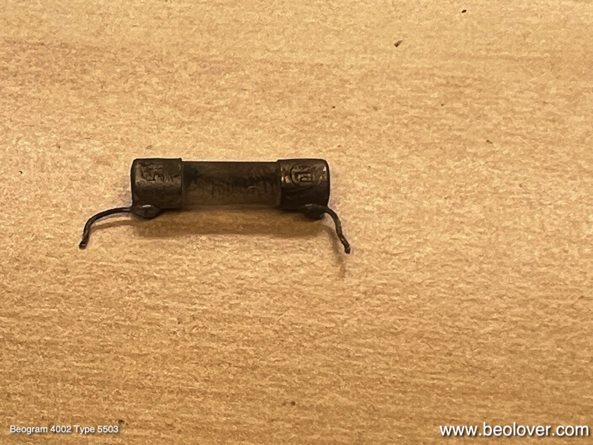
Like many AC-motor Beograms this one also had a 'troubled' fuse F1. It is directly soldered to the PCB. I extracted it:
I measured its resistance, yielding ~13 Ohms. Way too high. So I replaced it with a new one. I had to solder the wires to it:
This shows it implanted:
Another weak point of the AC motor Beograms is the solenoid lever, which came with a riveted plastic extension for activating the solenoid current limiting switch. In all Beograms of this type that I came across so far, the plastic extension developed stress cracks around the rivet:
It is important to fix this since a missing extension will result in an overheated solenoid. I drilled out the rivet, which liberated the extension. This shows the separated parts, as well as my 3D printed replacement ready for bolting on:
This shows the replacement extension in place:
This shows the repaired arm in action. It properly activates the solenoid switch:
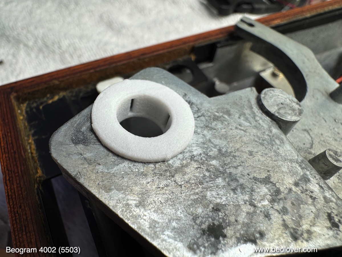
Finally, I also replaced the as usual hardened damper gasket with a new one:
This ensures a consistent arm lowering experience. 
This Beogram is now updated to the latest 'Beolover restoration standard'! I will play it for a bit and then it will return to its owner in California.