Featured Post

Beolover SyncDrive: DC Platter Motor Replacement for Beogram 4002 and 4004 (Type 551x and 552x)

Late Beogram 4002 and the 4004 (Types 551x and 552x), which have DC platter motors instead of the earlier synchronous AC motors usually suff...

Showing posts with label motor capacitors. Show all posts

Thursday, April 10, 2025

Beogram 4002 (5503): Intermittent Tracking, Installation of New Carriage Motor and Restored Keypad and Update to Latest Beolover State-of-the-Art

I recently received a Beogram 4002 (5503) that I had restored in early 2020. After running for a while it came back in August 2023 with a fried H-Bridge. The H-Bridge is responsible for driving the DC carriage motor. It allows reversing the current direction even if there is only a single positive voltage rail in the system. It does that with transistors that act as switches to reverse the polarity on the motor leads. These transistors need to be able handling the motor current. If everything goes well, the current capacity of the transistors is safely above the current drawn by the motor in all operational situations.

Electric motors draw more current when they run under load since they run slower at the same applied voltage. The slower RPM causes the motor back-EMF (the self-induced voltage in the motor, which is opposed to the driving voltage) to be lower, so more of the applied voltage arrives at the motor coils, which in turn increases the current in the motor windings. This is a great feature of electrical motors since it means maximum torque at zero RPM, great for burning some rubber at a green light to impress ICE vehicle drivers (whose torque-to-RPM ratio is reverse: Minimum torque when the car is at rest and maximum torque when it is at speed...;-).

But this also means that if a mechanical system that is driven by an electrical motor develops more friction over time due to hardened lubricants or dry motor bearings, the motor will draw more current than when the system was new.

I finally came to realize over the years that this may be the root cause for H-bridge failures in Beogram 400x. The H-bridge transistors are able to handle currents of 1 Amp max. And when everything is according to spec fast forward or reverse typically draws about 0.1-0.2 Amps. 5x is a decent safety margin. But when there is additional friction, the current can get dangerously close to 1 Amp or even exceed it. This is evident from the often found blackened PCB surfaces under failed H-bridge transistors.

The main reasons for this issue are the carriage motor itself and hardened lubricants in the carriage translation mechanism. The latter can easily be addressed by cleaning and re-lubricating, but in the case of the motor replacement is necessary. In difference to the later DC platter motors, these motors cannot be rebuilt easily. This was the reason I designed a replacement motor that draws less current than the original motors at a similar torque. Due to its modern design it also creates less vibrations and noise compared to the original motors. This post describes an evaluation of my design.

So I am not really surprised anymore that this Beogram came back again with carriage drive issues considering the earlier H-bridge issues. This time it sometimes stopped tracking. An indication that the carriage motor developed even more friction in its bearings since the last visit. 

Therefore, the first step was to replace the carriage motor with the new Beolover Carriage Motor for Beogram 4000, 4002, and 4004:

This shows the original motor in place:

I extracted it and opened the enclosure up:
Then I installed a new Beolover motor:
It is a bit shorter, which permits feeding the leads through the hole in the enclosure bottom for convenient routing. This shows the motor in place:
After the motor I also replaced the H-bridge power transistors, which were potentially compromised due to the too high current draw of the carriage motor. This shows the H-bridge as I left it in 2020:
I removed the four transistors:
1TR25 definitely got a bit hot as suggested by the browned PCB surface under it. This transistor participates in driving the carriage left towards the home position. This is probably the most stressed one since every time the carriage returns home it goes full speed for maybe 20 sec giving this transistor some time to heat up.
I installed a new set of transistors and then it was time to update the RPM panel backlight LEDs. I had replaced the bulbs in 2020, but back then I still used homemade boards featuring red/green LEDs tuned to yield an incandescent sheen. This shows the bulb covers of the RPM panel:
I removed the covers, which revealed the LED boards I had installed:
I removed these PCBs. This shows the old design together with my current solution:
The new boards solder directly to the solder points of the original light bulbs. They essentially act as an extension of the circuit board. This shows them installed:
They give the RPM adjustment scales a nice incandescent-like backlight:
My customer also wanted me to update the main capacitor setup and the wasteful linear regulator based 22.8V power supply. This shows my work of 2020, when I still used big radially leaded capacitor cans similar to the original setup:
This board solders directly to the existing leads that previously connected to the big capacitors. The board also replaces 0TR1 (to the right of the platter motor in the picture) that regulates the 22.8V rail in the original setup. My board uses a modern buck converter to create the system voltage from the rectified DC coming from the transformer, which is much less wasteful and results in a cooler running and less energy using Beogram.
Looking at my notes from 2020, I saw that I did not de-magnetize the solenoid plungers yet as a standard restoration item. These plungers often get magnetized to various degrees, which can result in sluggish arm lifting. During auto-return at the end of a record this can cause the tip to drag over the platter for some distance before it finally lifts up when the spring overcomes the magnetic attraction. For demagnetizing the plunger the solenoid has to be extracted and then the plunger unscrewed from the angled bolt that connects the solenoid lever. This shows the solenoid in place:
Indeed the extracted plunger was magnetic. I usually test this with a ferrous set screw. If the plunger attracts the screw it needs demagnetizing:
After using my tape head demagnetizer on it a bit the screw was not attracted to the plunger anymore, 
so I put everything back together.
I also found that the sensor arm LED replacement was still one of my early versions based on a home etched flex PCB that I folded into the small bulb compartment:
This shows the extracted old part in comparison with my current approach, based on a small PCB and a 3D printed alignment aid:
This shows it in action. It uses a warm white LED that has enough red photons for lighting up the B&O logo in a realistic warm red:
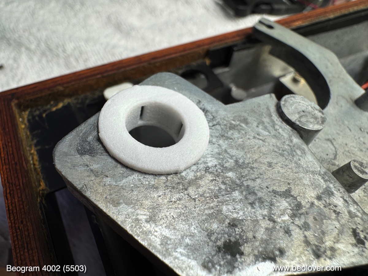
Next came the replacement of my original early design transport lock bushings. The one on the left in the picture below shows my original design, which has a much wider wall thickness. Over time I came to realize that it makes the adjustment of the sub-chassis much easier if there is a bit more room around the lock bolts. So I re-designed the bushings with thinner walls (shown on the right): 
An added nice benefit of these new bushings is that the sub-chassis can move much more before it hits the lock bolts. This gives gives it a much more supple feel when the platter is touched and just freely swings. This shows one of the bushings installed:
Their two halves are simply pushed in from the top and bottom, which makes installation very easy. This shows the liberated chassis during the installation of the bushings:

The final update was to replace the smudged keypad with a new Beolover replacement. This shows the original keypad:
Most of the 4002 and 4004 keypads develop such use traces over time. First it starts with such 'smudges', basically polished areas caused by friction with the fingers when operating the Beogram. As time goes on the coating wears fully through. Luckily co-Beolover Beomazed recently succeeded after a long time of trial and error with reproducing the keypad plates. His plates are completely new and carry a modern resilient coating that promises to last for a while. This shows the restored keypad:

Absolutely stunning. They really look like the original pads! Read here how he does it!
If you are interested in getting your keypad restored, please visit here.
I installed the renewed pad in the Beogram. This is how this beauty looks now!:
And then it was finally time to enjoy this fully Beolover state-of-the-art restored Beogram with one of my favorite records by Chico Hamilton: "chic, chic, chico", which he recorded in 1965 on Impulse! I have the stereo version AS-82. He looks really chic on this one!...;-). A stunning record that has just the right amount of 'avant-garde edginess' as one would expect from an Impulse! record! A great match for this beautiful Beogram 4002!:
I will now play a few more records on this deck and then it will be time to send it back to its owner in California!


Friday, July 12, 2024

Beogram 4002 (Type 550x): New Main Capacitor Array with Integrated Efficient 22.8V Power Supply

Immediately after offering the new Beolover Efficient 24V Power Supply and Main Capacitors for Beogram 4000 component, I received inquiries about whether this part could also be used in AC platter motor Beogram 4002s (i.e. Types 550x).

The earlier AC-motor 4002s have a fairly similar setup when it comes to their main power supply. But there are minor differences: The rail voltage is only ~22.8V instead of 24V, and they do not splurge on a continuously powered standby mode like the Beogram 4000. But they also waste a similar amount of energy during operation due to the fact that the 45V transformer voltage is regulated down to the specified 22.8V with a Zener stabilized power transistor. This results in a nearly 50% energy loss in the 22.8V rail in the transistor.

In my design for the Beogram 4000 I replaced this setup with a modern buck converter-based design that has a DC-DC conversion efficiency in the 90-95% range. This causes the Beogram 4000 to run much cooler due to the reduced heat load. I provided a basic analysis and explanation of this setup in my original post about this design.

While the voltage difference is not really an issue, unfortunately, the different turn-on method in the 4002s without stand-by prevents the direct use of the Beogram 4000 board in the 4002s. Therefore, I designed a dedicated board for 4002s that also directly replaces the main capacitors and the voltage regulator setup. This is how the new board looks (it is available for purchase at the Beolover Store):

The many round capacitors are high-quality 105C rated Panasonic electrolytic capacitor arrays that provide the new power supply with appropriate reservoirs and couple the motor to the Wien oscillator amplifier. The row of small 'boxes' on the left is an array of Samsung X7R type ceramic capacitors that add up to the 150uF of the non-polar original electrolytic motor phase capacitor. Ceramic capacitors are much better for this application since they are inherently non-polar and they can take AC current much more easily than electrolytic capacitors. The circuit on the far end of the board is the buck converter based 22.8V power supply.

It replaces is this original setup:
The two larger capacitors on the right (0C1/2) are the in parallel connected reservoirs for feeding the voltage regulator whose transistor (0TR1) is bolted directly to the chassis right of the motor. The reason that this transistor is not on the main PCB is its significant heat dissipation that needs to be sinked efficiently. A significant part of the energy going into the Beogram is leaving it as heat at this front corner. That is the main reason that this area gets pretty hot after playing a couple records. Motor and transistor pretty much divide maybe 40% of the total heat load of the deck between them. The rest is mostly dissipated from the transformer, the solenoid (when the arm is down), the Zener that controls the regulating transistor, the incandescent light bulbs and the electronics.
The other two capacitor cans are to couple power into the motor (0C3) and to shift the motor phase by about 90% for the second winding (0C4).
This is a snippet from the circuit diagram showing the setup of the original power supply:
The buck converter that is integrated on the board basically replaces the 0TR1 transistor eliminating most of its power dissipation.

Replacing this setup with the new Beolover board is straight forward. Simply remove the capacitors and then unsolder all the wires from them and the transistor:
The transistor can/should be left in place.
Then solder the wires that were connected to the transistor to the respectively labeled pads at the bottom end of the board:
Then connect the four wires from the motor according to their color:
Here a shot from a bit further away:
Then solder the red and black wires from the rectifier:
A detail photo:
Next are the wires that go towards the PCBs: The green wire goes to the pad next to the motor wires, and the two orange and black wires to the pads on the right of the rectifier wires:
And that is it: This shows the board fully connected and bolted in:
And with the main board replaced:
Beolovely!
Like for the Beogram 4000 setup, I also measured the temperatures and currents before and after. This is what I got (33RPM, 13.2V motor voltage, arm up and carriage at rest):

Similar to the results for the Beogram 4000, a significant drop in temperatures occurred: The motor temperature dropped from 47C to 38.4C, while the temperature at the transformer went down from 38C to 34.8C. As a consequence the deck does not feel unusually warm anymore to the touch.


Saturday, June 22, 2024

Beogram 4000: New Main Capacitor Array with Integrated Efficient 24V Power Supply

If you ever experienced a Beogram 4000 you probably know that it gets pretty warm after a while! The main reason for this is the 1970s style voltage regulator based power supply, which is a bit of an energy hog.

So when I decided to replace my main capacitor replacement kit with a more modern PCB based design, I thought, why not integrate a modern buck converter based 24V supply that would smoothly replace the original 24V regulator?

This is the new design that resulted (it is available for purchase at the Beolover Store, there is also a version of this board for the AC motor Beogram 4002 Type 550x):


The many round capacitors are high-quality 105C rated Panasonic electrolytic capacitors that are connected as an array to match the original reservoir capacitor values. The row of small 'boxes' on the left is an array of Samsung X7R type ceramic capacitors that add up to the 150uF of the non-polar original electrolytic motor phase capacitor. Ceramic capacitors are much better for this application since they are inherently non-polar and they can take AC current much more easily than electrolytic capacitors. The circuit on the far end of the board is the buck converter based 24V power supply.

And here an impression of an installed board:

It bolts directly into the mounting holes of the capacitor clamps of the original setup. The solder pads for the wires are in approximately the same locations as the original connections to the big capacitor cans. This makes it straight-forward to replace the old capacitors. Simply unsolder them and then tack the wires to the pads according to position and color labeling.
This is an impression of the original setup that is being replaced by the board:

This schematic tries to make sense of the wiring around the capacitors and the voltage regulator:
For the installation of the new board this diagram does not need to be fully internalized. Simply match the colors of the wires with the labels next to the solder pads. This shows the board with all the connections in place:
Note that the 'thin blue wire' from the collector of the original voltage regulator (see below) needs to be moved over to the PCB. Solder it to the pad labeled "lgt. blue" up front where also the orange wire is connected. The blue wire connects the solenoid to the 45V coming from the rectifier.

Let's discuss the Beogram 4000 24V power supply a bit. The 24V rail is the main supply and energy provider of the Beogram. The motors, light bulbs as well as the circuitry that translates the commands from the 6V powered control logic beneath the keypad into actual behaviors of the Beogram are powered by it. The 6V supply that provides power to the control logic is only a marginal energy consumer since it only drives the logic chips producing control signals.
This is a clipping from the circuit diagram that shows the 24V setup (the red dotted rectangle indicates the parts replaced by the new Beolover board):
The rectifier 0D1 is fed about 46-49V RMS from the transformer secondary. The rectified voltage is smoothened by capacitor 0C3 into an unstabilized DC voltage of about 45V. This 'rough' DC voltage is fed into the collector of 0TR1, which is set up as an emitter follower controlled by a Zener stabilized ~24V voltage at its base. At the emitter of this voltage regulator a second big capacitor 0C4 removes most of the remaining DC ripple and a stabilized ~24V rail results.
This picture shows how this circuit is implemented in the Beogram 4000:
Since this regulator circuit produces a large amount of waste heat in the transistor, the transistor itself is bolted directly to the metal enclosure in its own metal compartment. This makes for an effective heat sink. The collector of the transistor is connected to the metal bar that clamps the transistor down (the screws go in from the bottom of the enclosure). Left and right of the collector bar the base and emitter leads poke out through insulating sleeves. The big maroon colored resistor on the left is 0R1, which pulls the Zener up to the unregulated 45V from the rectifier, which is connected to the collector bar via the red wire seen on top of the picture. The Zener itself is the metal can whose cathode is soldered to the base. The anode end of the Zener is anchored to GND, which is achieved by soldering the lead to the connection point of the two negative terminals of the biggest (3000uF) capacitor cans of the setup, which are also connected to GND via the black and green wires (see schematic above).
The blue wire that goes to the same solder spot like the red wire connects directly to the top of the arm lowering solenoid. In other words the solenoid directly gets the unregulated 45V and bypasses the 0TR1 regulator (this wire needs to be moved to the Beolover PCB during installation).
I think this explains why the B&O designers chose to regulate 45V down to 24V. The solenoid needs such a high voltage to actuate reliably, and apparently they did not see fit using a transformer with a 3rd dedicated secondary winding for the 24V rail. I guess in the 1970s it did not really matter that much if a device wasted almost 50% of its energy intake...;-), because this is about what this approach 'achieved'. 
Let's have a look at different ways that can be used to convert a voltage down:
This figure shows the three main ways to go from a higher voltage to a lower voltage:

The most straight-forward way is a simple voltage divider. In this figure the 'load' represents the entire 24V connected circuitry of the Beogram. If we want to go from 45V to 24V, we simply calculate R1 according to R1=((45V-24V)*R(load))/45V and as long as the load resistance remains stable we have 24V on the load. The problem with this setup is that the current is the same in R1 and through the load. In the case 45V->24V this means that R1 dissipates almost the same heat as the load, so close to 50% of the energy is directly wasted into heat.
The next step up is the voltage regulator like it is employed in the Beogram 4000. Here we replace R1 with an emitter follower and a zener/resistor divider that puts 24V on the base of the transistor. The great improvement with this approach is that it can keep the voltage pegged to 24V regardless of variations of the load resistance. In the Beogram example, the load resistance would for instance go down as soon as the platter motor turns on, which would draw more current. Whenever the carriage is moved the load resistance goes down a little, too. And so on, bulbs on/off etc....
Since loads are rarely constant, the voltage regulator is a popular and simple way to achieve a regulated stabilized voltage rail.
But since the emitter follower basically only replaces R1 and essentially still acts as a resistor, albeit a variable one, we get a similar heat dissipation like in R1 in the simple divider. In fact, it gets even worse, since we have to feed the Zener divider, which constantly carries a current to peg the base to 24V. This current is actually fairly substantial in the Beogram setup since the regulator is a simple bipolar power transistor with a low gain, maybe in the 25-50 range. This means that the base needs to constantly carry a current that is a few percent of the collector-emitter current through the transistor into the 24V rail, proportionally increasing the heat load. Hence the big 5W power resistor!
While this approach was maybe the best approach in the 1970s, it is not used much anymore in modern designs since we have now MOSFET transistors, which can switch at high speeds with a very low heat loss due to their very low ON resistance. This enabled the development of the so called buck converter, which is able to step down voltages with high efficiency. Modern designs can achieve 90-95%, minimizing heat loss dramatically.
A very simple schematic model of such a converter is shown in the above figure. At its heart the R1 resistor is replaced with an appropriately dimensioned inductor. This inductor acts like a resistor plus energy storage due to the fact that a coil upon turn-on has a high resistance due to the EMF that is acting agains the inrush current. As the magnetic field builds up in the coil the resistance drops asymptotically towards zero. So in the end a coil is basically like a straight wire with some residual Ohmic resistance.
So how do we go from 45V to 24 with this process? This is achieved by chopping the 45V input into a high-frequency 'pulse width modulated' (PWM) signal. This results in a continuous partial ramping up of the current in the coil during the ON 'duty' cycle, and a release of the stored energy in the coil into the load during the OFF (-duty) period when the voltage is cut.
As a consequence, most of the energy in the 45-24=21V drop that is wholly dissipated in the divider and regulator circuits is instead fed into the load!
Pretty cool (in the literal sense of the word!...;-)! Of course, nothing is free in nature, and the disadvantage of this setup is that there is a bit of noise on the output voltage caused by the incessant chopping of the input voltage. This is dealt with by connecting a reservoir capacitor across the load, which stabilizes the voltage. 
The above basic circuit also omits the necessity of a feedback based control circuit that adjusts the PWM duty cycle depending on the load resistance to keep the voltage on the load constant. So this setup is in reality quite a bit more complicated than the simple regulator circuit of the Beogram. Luckily, one does not really have to deal with this 'complication'. Nowadays integrated circuits take care of all of this and one simply has to select the right external components (i.e. resistors, capacitors and the inductor) for the desired output voltage and current needs.
The two traces at the bottom of the above figure show the result of the simulation: The chopped input voltage (green) and the resulting ripple on the output voltage (blue). With a fairly modest 100u cap the ripple comes out to about 27mV, or ~0.1% of the output voltage. The Beogram has 3000uF at the output (0C4), and so it is much smaller, probably easily in the range of the original regulator output.

Let's have a look at the actual 24V supply circuit on the new Beolover board:
The big 'box' in the back is the inductor and the small 8-legged integrated circuit in front is the buck converter. The passive components around it take care of the feedback to keep the voltage constant.

Alright! On to some measurements! I measured the current draw into the 24V rail and the temperatures of the transformer and at one of the screws that bolt the motor down before and after the implantation of my new board.
It is important to state the motor voltage at which these measurements were made since this voltage directly influences the current draw of the 24V rail. This is a oscilloscope trace measured at the purple lead (the nice sine wave also demonstrates that my ceramic capacitor array works happily as motor phase capacitance):

The 13.3V amplitude I chose balances enough motor torque for sweeping dust off the record with a still reasonable current draw.
The temperature measurement location at the motor made sense since the voltage regulator is directly next to it and so I would measure the heat in the front left corner, coming from the motor and the regulator. This shows my measurement setup (Beolover PCB already installed):
The temperature meter above shows the two temperatures and the multimeter is hooked into the 45V line as current meter. The picture shows the current draw in ON condition with running platter. About 190mA go into the 24 power rail. This table shows the measurement results for the original setup vs. the new Beolover 24V supply:

The current difference in OFF condition is 70mA vs. 15mA (original vs. new) and 360mA vs. 190mA. We see that the power consumption of the 24V rail goes down by almost 50% in ON condition and about 80% in OFF (standby) condition. The better performance in standby comes from the absence of the Zener diode voltage divider, which is absent in the buck converter circuit on the Beolover board. In OFF condition the Zener divider represents the main power draw of the 24V rail.
The standby power draw of the original setup of 3.15W is pretty impressive. Considering the hours in a year (8760), this means that over a year about 27kWh are dissipated by a Beogram 4000 just by sitting on the shelf being plugged in. This is reduced to about 6kWh with the new Beolover circuit. Just to put it in perspective, 1kWh allows driving a typical electrical vehicle for about 2-3 miles. So this is a pretty substantial power waste for a standby audio device. 
This more frugal power consumption of the Beolover circuit became immediately evident in my temperature measurements. The original setup reached 47C at the motor and 41C at the transformer in ON condition (after about 1 hr runtime). In contrast, with the Beolover board installed much lower temperatures of 37C and 34C were measured, respectively. 
So in conclusion one can say that the Beolover board reduces power intake of the 24V rail by almost 50% while playing the deck, and by almost 80% while it sits in standby.
This Beogram 4000 has arrived in the modern age in power supply terms!