Featured Post

Beolover SyncDrive: DC Platter Motor Replacement for Beogram 4002 and 4004 (Type 551x and 552x)

Late Beogram 4002 and the 4004 (Types 551x and 552x), which have DC platter motors instead of the earlier synchronous AC motors usually suff...

Showing posts with label power supply tests. Show all posts

Friday, May 14, 2021

Beogram 8002 From North Carolina: Finishing up the service manual adjustments

I was able to get quite a lot done since the previous post.

I performed the power supply tests, adjusted the tracking force by calibrating the tonearm counterweight, adjusted the tracking sensor setting and adjusted the forward/reverse scan LDR voltages.

To begin with here are the supply voltage checks from the supply filtering capacitors for +5V, +15V and -15V.


I also measured the regulated +5V that goes to various places in the Beogram 8002 (including the microcomputer board).


In this earlier post for this Beogram 8002 I had to fix the tonearm counterweight.
Now it was time to calibrate and adjust the tonearm for 1 gram of tracking force.
For the tracking force adjustment and the record tracking sensor adjustment that will follow I don't want the Beogram 8002 platter to rotate when the turntable is on.  To facilitate that I unplugged the P4 connector on the main PCB (with the Beogram AC plug disconnected as well of course).


The other test wires connected (temporarily) to the back of the main board are for monitoring some key Beogram 8002 signals with an oscilloscope.  I will make those measurements later in this post.

For the tracking force calibration and adjustment I installed a cartridge on the tonearm and set the tracking force to 1 gram.  Next, I adjusted the counterweight position using the set screw until my tracking force scale measure 1 gram.


Now that the tracking force is set I ran through the tracking sensor adjustment steps.
For this adjustment a test record is set on the platter.  The platter drive is still not connected so it can only be turned manually.

The procedure says to lower the tonearm with the cartridge stylus onto a record groove.
The platter is turned manually while observing the Beogram 8002 servo motor (tangential arm assembly motor).  The servo motor should advance the tonearm the first time within 2 platter rotations...plus or minus 1 rotation.  So between 1 and 3 rotations.  After that the servo motor will perform advances as necessary. It is a good idea to use the same test record(s) for this adjustment as the record grooves vary between vinyl records. Using the same set of records for the adjustment will allow the setting to be consistent.

The service manual refers to the tracking sensor adjustment screw as "screw B" shown here.
Note the tracking sensor lamp illuminating from inside its housing.  If that lamp is not on then of course replace that first.  I don't believe I have ever come across one that was out on a Beogram 800x turntable.


After a few iterations and the adjustment check performed on two different test records that I like to use, I was satisfied with the result.

I unplugged the Beogram 8002 AC plug and reinserted the P4 platter drive connector.
Then I plugged the Beogram back in and tested its play of a record.


One last adjustment is on the forward and reverse scanning control sensors.  The forward and reverse scanning buttons press a spring loaded aperture between a light source and an LDR. Two LDRs actually.  One for the forward scan and one for the reverse scan.  The change in the light through the aperture determines the scanning operation.
The steady-state (no scanning) voltages on those LDR sensors should be adjusted to around 620mV.
The adjustment for the LDR voltages is via a large screw at the back of the button panel. One for the forward LDR and one for the reverse LDR.


This is an important adjustment on the Beogram 8002.  If the scanning LDR voltage level is far enough off, the Beogram 8002 tonearm movement will not operate properly.

I have always found it very inconvenient to make this adjustment as it requires opening the Beogram 8002 into its service position. 

There are often cases where I want to double-check the scanning LDR voltage levels after the Beogram 8002 is reassembled in its cabinet.  Opening it all back up just for this measurement and adjustment is a pain.

For that reason I started installing a small test connector that I leave in the Beogram (both the 8000 and 8002 turntables).  With the test connector I can later make the measurement and adjustment again by only popping off the Beogram button control panel. It is easy to remove and reinstall.

Here is the Beogram 8002 button control panel removed for installation of the test connector.
The spring loaded aperture controls for the scanning LDRs are shown highlighted in the photo.


Here is the test connector I install.  The connector and its 30 gauge wiring will easily fit into the Beogram 8002 out of sight when the turntable is reassembled into its cabinet.


To use the test connector for the LDR adjustments I just plug in my three pronged test leads and make measurements with a DMM.

This photo shows the adjusted LDR voltage for the Reverse LDR sensor.


Very nice.  It is great to see the Beogram 8002 operating correctly again.

Now...while I have my test wires hooked up to the main board I collected some screen shots of the following signals at various modes of operation for the Beogram 8002.

The signals I wanted to observe are the Record Detection Sensor, the Platter Speed sensor and the two sensors on the tangential arm drive spindle.


Here are the oscilloscope measurements of those signals during various Beogram 8002 operating modes.

As a reference, here are the signals when the Beogram 8002 is off.


Here are the signals when pressing the Play button.


Here are a couple of pictures of the signals when the Beogram 8002 is returning home after searching for a record on the platter.  You can see that different patterns of bands on the Beogram 8002 platter affect the Detector Arm signal. Notice the difference in relative position between the two position sensor signals in these reverse direction photos and the previous, forward direction. They swapped positions on the oscilloscope trace.




Finally, here is a trace of the signals when a record is playing. This trace triggered on position sensor 2 in order to catch the activity by the servo motor advancing the tonearm. Note that the Detector Arm signal is silent as there is a record on the platter.  


It isn't a requirement to measure these signals during a Beogram 8002 restoration but I wanted to start collecting some reference photos to have in comparing the turntable restoration projects I have been working on.  They provide another visual reference of the turntable operation.

Tomorrow I will work on the Beogram's dust cover hinge repair. 
After that it will be ready to reassemble and move on to some record play testing before going home.


Sunday, July 22, 2018

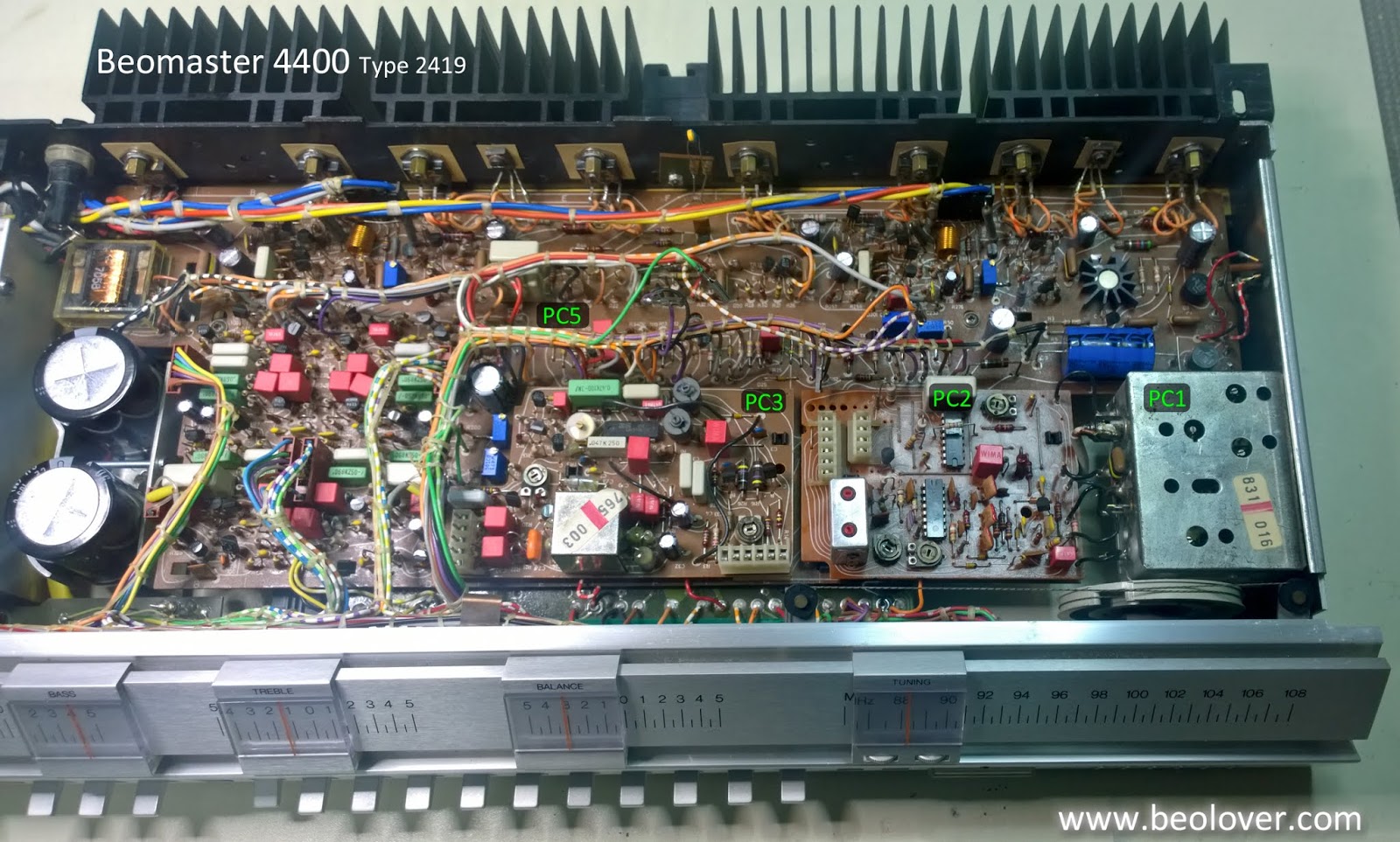
Beomaster 4400 (2419): Reassembly and Power Checks

Today I reassembled the electrical components of the Beomaster 4400 and performed the all important first power on test. The goal here was to verify all of the board component work is correct and the Beomaster can be plugged in, turned on and all of the power supply voltages are good.

I installed the FM boards (PC1, PC2 and PC3) first.


I had removed the shield cover to the main power switch so I reinstalled those parts now.


The last board to install is the PC4 preamplifier board.


As I was tightening the mounting screws of the preamplifier board to the cabinet I was reminded of a problem (in my opinion) with the design of the connector panel. The RCA jacks are too close together. This is also the case on the Beomaster 4000 receiver. I don't own any audio cables with RCA plugs that can mate with the Beomaster 4000 and 4400 receivers. The only solution will be to make my own and use heat shrink tubing instead of the outer shell that comes with the RCA plugs.


You can see that only the bare RCA plugs can fit the space allotted by the Beomaster connector panel.

I always connect Bang & Olufsen source components to the Beomasters so it isn't a problem for me but it is something to be aware of if you are planning on using your Beomaster 4400 for some non-B&O audio source components. The solution in that case is to get an adapter cable that goes from the RCA plugs to a 5-pin DIN plug.

Anyway, just a pet peeve on my part. Continuing on it is time to see what happens when power is applied to this newly recapped Beomaster 4400.  In the case of the older Beomaster amplifiers I like to use a variac with a dim-bulb tester on the first power up. It is just added protection in case I missed something. 


The Beomaster 4400 powered up fine. That is great so now I checked all of the DC voltages in the Beomaster.

Here is the +15 VDC power check where the regulator 0IC1 attaches to the PC5 board.


Next is the +35 VDC rail voltage at TP3 of PC5.


Then the -35 VDC rail voltage at 5R16 of the PC5 board.


I checked the +24 VDC voltages at the emitters of 5TR3 and 5TR4.  Here is a picture of the 5TR3 emitter. Both measured +24 VDC as they should.


Last I checked the -12 VDC at TP15 of PC5.


Very nice. Everything looks good so far. Tomorrow I will start adjusting the no-load current (idle current) and the source levels. Once that is done I will be able to see how this amplifier performs with audio signals.

Tuesday, April 24, 2018

Beomaster 8000: Power Test Update

The +15V regulator is now functioning correctly on this Beomaster.


The next thing to do is recheck the no-load current and the DC offset adjustments again.


I did both channels and no problems with those adjustments. I didn't expect any since I had already tested these output amplifiers by themselves earlier.

I usually do a first listening test using the Beomaster TP2 source once I am confident the amplifiers are ready. This unit fired up and played just as beautifully as I expected.


I performed the same check on TP1 and it played great too.

After an initial scare where the FM tuner wasn't producing any sound, it turned out the problem was only a faulty connector not making contact. I fixed that and the FM tuner also works great. The signal meter and tuning display indicate the FM board is picking up stations.


A good second test overall. The power supply tests all pass now and I was able to successfully recheck the output amplifier settings. Best of all I got to hear a nice preview of this Beomaster playing music again.

The next steps are the obvious display segment repair and I will do the preventative update of the microcomputer oscillators.


Sunday, April 22, 2018

Beomaster 8000: First Power Test

The Beomaster 8000 boards are all recapped. The output amplifier boards were exercised and passed their bench test. The remainder of the components have to be tested reassembled in the Beomaster so I think now is a good time to see where I am actually at with this restoration.

I want to check the Beomaster power supply with everything back in the cabinet. I also want to see what the condition actually is on the microcomputer and display boards. Since this Beomaster arrived in a non-working state I don't really know if those two boards have any issues aside from the electrolytic capacitors.

So here goes...
It is difficult to really document clearly with pictures where every cable connection goes. The best thing to do is label the connectors as you are disassembling them and take lots of pictures.

Here are a few pictures of the reassembly of the Preamplifier, FM, FM Interface, Filter & Tone Controls and Microcomputer boards.


After a double and triple check of the wiring I plugged the Beomaster power cord into my bench AC power strip. This looks promising. It means I at least have +5V power.  The Beomaster correctly comes up in Standby mode.


Time to check the voltage regulators.
First the +5V even though I know it has to be working. I still want to measure the input and output of the regulator.


Very nice.

Now to check the ±15V regulators. I like to use TP1 or TP2 mode to first take the Beomaster out of Standby.  I selected TP2 in this case and that quickly reveals the display segments do have faulty LEDs.  I was expecting that but it needed to be confirmed.


Checking the -15V regulator I can see its input and output are good.


Not good news on the +15V regulator. The output is bad.


That isn't a big deal though as these regulators are easy to come by and the location of the component makes it easy to replace.

I also checked the ±55V reservoir capacitor voltages. This picture shows that it is at 56V which is fine.


I am happy with the test results. Nothing major.  Importantly, the microcomputer appears to be great. The display board has bad segments but the plan was to change those LEDs out anyway. The +15V regulator failure should be easy to deal with. I will replace the regulator, proceed with the display LED replacement and perform the preventative measure of replacing the microcomputer crystal oscillator devices.

That should keep me busy for a while. Once those steps are complete I should be able to put the Beomaster in operational mode, recheck the no-load current and DC offset in the output amplifier and give the receiver a listen.