Beolover provides professional maintenance and restoration services for vintage Bang&Olufsen stereos. We give one year warranty on parts and labor. All parts featured on the blog are available at our Store for DIY. Please, send an email for inquiries. Enjoy the blog!
The Beogram 4002(5513) that I am currently rebuilding will be used together with a McIntosh Preamp, i.e. the DIN5 connector that is standard on Bang & Olufsen equipment is inconvenient. The best solution with regards to shielding and lowest-possible EMI is to install a new cable with RCA connectors right at the source of the signal inside the turntable. Adapters are never a perfect solution.
Aiming for excellent sound quality, we decided to go with an solder-ready open ended RCA cable supplied by Sounds Heavenly in the UK. This cable features individually shielded left and right cables using a twisted-pair arrangement between signal and return path. At any rate, it looks very 'audiophile'...;-). I made a short video discussing the original DIN 5 arrangement, the installation of the RCA cables, and the differences between the 4002, 4004, DIN and RCA grounding and shielding schemes:
Here are a couple pictures of the installation. This one shows the new cables installed into the original plug of the DIN 5 cable:
And this shows the cable entry to the Beogram and the RCA plugs:
The 'beautification stage' of my current Beogram 4002 (5513) restoration continues: The final touch was to re-attach two delaminated keypad sections. Here is a picture of the issue:
I put a bit of superglue gel under the pads and clamped them down with vise grips:
One needs to be careful to not put too much glue there, since any excess can potentially reach the top of the pads, whose delicate paint surface can easily get irreversibly damaged by the glue. So my recommendation is to start with very little glue and see if it holds. If not put a bit more. Patience always pays off with such projects...;-).
This one worked out well the first time. All good now in keypad land:
While I was waiting for the pseudo balanced 'audiophile' RCA cables from Sounds Heavenly, I gave the cabinet of the Beogram 4002 (5513) some TLC. The cabinet was cracked on both corners, and all the guiding washers that hold in place and enable its sliding action were missing. Here is a picture of one of the corners:
It is easy to glue them back together since the cabinet is held together by metal bands. So all one has to do is to put some glue on the wood surfaces and hold it together with carpenter clamps until the glue is dry:
Much more beautiful after glueing the cabinet back together:
This picture already shows one of the new 3D printed guiding washers installed (this one is under the key pad). They enable the cabinet to slide on a precisely defined path (as demonstrated in my YouTube video about the washers). So if you have a 'wiggling' cabinet, then it is time to check if these washers are still there. They were originally made from a flimsy plastic that cracks and degrades over time (B&O realized that soon, and the 4004 models have metal reproductions of them...but the 4002s have usually the (missing) plastic ones. Here is a picture of the replacements. One needs five of them:
Here are the four other locations where I installed them on this Beogram:
Not much left to do except implanting the RCA cables and glueing the two side-tabs of the keypad back down (one can see one of them sticking up a bit on the picture above left of the 'START' label). A Beogram 4002 well on its way to a full recovery!
A happy moment in Beolover's lab: Just received a quite pristine copy of a 1976 recording of Herbie Hancock's "Secrets" album (Columbia CA 34280). Almost looks like it was never played. I just love this record. I think my favorite track is "People Music". It has some lovely spaced out sections with awesome 1970s analog synthesizer sounds (apparently on a "Maestro Universal Synthesizer System").
I decided to play this record on the Beogram 4002(5513) that I just rebuilt. It is connected to my Beomaster 6000 4-Channel right now for testing. The Beogram is still apart since I am waiting for a RCA pseudo-balanced cable from Sounds Heavenly to complete the job. This beauty will be used on a McIntosh pre-amp that has RCA inputs. Anyway, here are a couple impressions of my bliss:
Note the nice almost-parallel alignment of the tone arm relative to the sensor arm:
I appears that Bang & Olufsen manufactured at least two different versions of the Beogram 4002 (5513) model with regard to the power supply. It seems that all of them were designed with a potential upgrade to a CD4 set-up in mind, i.e. the output board that normally only contains the output relay could be exchanged with a board featuring a pre-amplifier and CD4 decoder. As far as I can tell at this point there were two methods to supply the CD4 board with power: One way was to connect it directly via P4 on the main PCB to the 30V power rail. These models only have a simple 4000uF reservoir capacitor.
The Beogram that I am currently rebuilding has it differently: It has a separate supply fed from an additional winding in the main transformer that has its own bridge rectifier and 1000uF capacitor. Here is the pertaining part of the circuit from my annotated Beogram 4002 diagram:
The dashed line indicates the additional CD4 power supply. The unit was outfitted with a special capacitor that combined both the 4000uF main capacitor with the 1000uF CD4 capacitor in one package. Here is a picture of the original unit:
The GND contact for both capacitors is at the bottom of this unit. The contact at the front with the red dot is the 1000uF capacitor, while the second contact (white lead) connects to the 4000uF section of the capacitor. Of course, this type of capacitor is no longer available, which prompted me to replace it with two separate 1000uF and 4700uF capacitors to complete the recap of this Beogram. The question was how to mount them in the single bracket that held the original capacitor. I solved this problem by designing a 3D printed part that would fit into the bracket while housing the two individual capacitors. Here is a picture of the fixture (would you like it in red or blue??):
Here is a picture after installation:
And from the front:
And a detail pic of the wiring:
Of course, I could have abandoned the 1000uF cap and the CD4 power supply altogether since there is probably little chance that this Beogram will ever be upgraded to CD4. But my philosophy is to keep these units original and fully functional, hence I desired to keep everything intact (so that, once time machines are common, we can go shop back in the 1970's and get a CD4 board, and a few nice quadrophonic records...;-).
If you are interested the 3D printed adapter is available including fitting capacitors...just send me an email.
The Beomaster 4002 (5513) that I am currently restoring exhibited the usual issues with the tone arm lift mechanism: The mechanism occasionally failed to lift the arm up in time before the carriage started moving back (scratch & ouch!) to its home position after pressing the 'Stop' button, or at the end of the record. Also, the relay sometimes clicked before the arm was completely lowered. All this pointed towards time-hardened lubricants in the lift mechanism. The cure for this type of behavior is to take the mechanism apart, clean the old lubricants out and re-lubricate it with a suitable grease. I use a silicone grease. This type of grease is well-suited due to its generally non-corrosive behavior, its compatibility with rubber and plastic parts, and its long-term stability.
The restoration process is straight forward, but requires a bit of insight into the mechanism. For this reason I took the opportunity of this restoration to add a short video about the process to my Beogram 400x YouTube playlist. The video also shows how to adjust the arm lowering time to achieve precise coordination with the output relay activation. Here it is:
I used my current Beogram 4002 (5513) restoration project as a chance to redesign my earlier approach to replacing the incandescent light bulb in the linear tracking sensor with an LED. In my earlier approach (see here), I reused the bulb housing and just replaced the light bulb part with a 3D printed LED assembly that I had designed as an early (and later abandoned) iteration of my Beomaster 6000 4-Channel incandescent bulb replacement method. While this worked well for the Beogram, it had two significant issues: (1) it was not a drop-in ready solution and required a lot of detail-Dremeling of the original housing to get the glued-in bulb housing separated and replaced, and (2 - probably more important) that the LED position was not very well defined and also not impact/vibration stable. No(2) is clearly an issue when shipping the Beogram, i.e. not suitable for a professional restoration.
So I set out to design a part that is drop-in, 100% mechanically stable, and that is precise enough to only require a small adjustment of the tracking mechanism, which can be done by just turning the executer screw (larger adjustments require a cumbersome realignment of the sensor aperture). The adjustment process is shown in the video below.
Here is a picture of the original bulb housing:
It is interesting to note that the bulb is slightly misaligned, i.e. oriented to one side. I suspect that this reflects 1970's production tolerances, and that most tracking sensor bulb housings will have bulbs at various locations. The obvious consequence is that the installation of a bulb replacement will require the adjustment of the tracking mechanism after installation of the replacement part, independent of the part being an original-style incandescent bulb or a LED replacement.
I designed a part resembling the lower part of the original bulb housing, which is responsible for keeping stray light out of the tracking sensor. Then I combined this part with a custom designed printed circuit board that is responsible for operating the LED.
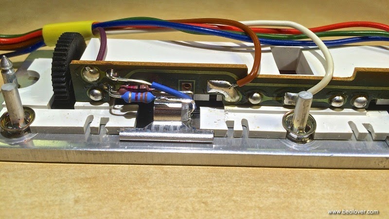
Here is a picture of the two parts before assembly. The LED is a standard white 0603 SMD LED run with a 2.5 kOhm resistance that it can take the 21V rail of the Beogram. The LED, resistor and the solder points of the leads fit into appropriate cutouts of the housing part:
Here is a picture of the running LED after epoxying the circuit board to the housing. The LED is precisely situated in the middle, i.e. very close to the bulb filament position of the original part:
I updated my earlier video about the tracking sensor light bulb replacement with the new part. It goes through all the steps of replacing the original bulb housing and discusses the tracking sensor mechanism. It also shows how a misaligned sensor behaves, and how to adjust it properly:
While I am waiting for a 3D print of the redesigned LED light assembly for the tracking sensor of the current Beogram 4002 (5513) I rebuilt the speed indicator scale lights with RGB LEDs. I essentially followed the approach demonstrated in my recent video:
Here are a couple pictures of the actually rebuilt unit:
Original set-up with incandescent bulbs (covers taken off):
And after replacement. There are two resistors since I am using the red and green LEDs of a RGB LED to get a naturally appearing light reflection on the red scale markers. Amber LEDs make an incandescent-like glow, but they do not contain red light, i.e. red scale markers show up gray and even invisible in absence of natural room light - this is discussed in more detail in the above video):
As usual, I further refined my approach a bit: One of the issues with LED replacements of incandescent scale lights is their considerably more narrow radiance pattern. Light bulbs emit fairly uniformly in all directions, while LEDs usually have a narrow emission angle. This is usually combatted by sanding the LED bulb, but some of the directional pattern remains, even after this procedure. In the above video I used tape to shield one end of the scales from too much light, which allowed me to achieve a mostly identical scale appearance as with the original light bulbs. And this worked fine for my personal Beogram 4002, but for a professional 'commercial' restoration I felt this is not a permanent solution, since tape ages and the adhesive can loose its force etc...Since my main interest is to make these beautiful turntables 'future proof' (Imagine Charlton Heston digging it out next to the Statue of Liberty on the beach, cleaning it and plugging it in and the scale lights work...;-),
I needed a more permanent solution. So this time I decided to carefully apply some black acrylic paint to the end of the bulbs and some to the exposed side. Here is a picture of my efforts:
After a few trials slowly adding more painted areas I ended up with this degree of coverage. It is important to also cover a bit of the side wall of the bulb cylinder to absorb some of the photons in that direction to get an even scale illumination.
I did a quick check on the sensor arm light bulb of the Beogram 4002 (5513) that I am currently restoring. What I found was a pristine bulb, not blackened at all. The bulbs that I so far encountered showed clear signs of filament evaporation, which results in a dark coating on the bulb glass. Not here:
Seems this Beogram saw only little use, or the bulb was replaced at some point. So I will not replace it. It is interesting, however, to note how it sits in its compartment. Absolutely straight on the wires that come in. This suggests that the reason my recent replacement of this bulb with an LED required a high intensity LED may be due to positioning the LED at the wrong location within the housing, i.e. not at the focal point. I will try again with a different set-up. I would enjoy a LED replacement that preserves the original incandescent glow...my high brightness white LED gives it an interesting back-to-the-future feel, but at heart, I really desire to restore these units to their original beauty, just with modern long lasting parts.
I started rebuilding the Beogram 4002 (5513) that recently was sent to me. Today I exchanged all electrolytic capacitors on the PCBs with 105C grade capacitors (I only use capacitors from major Japanese manufacturers such as Nichicon or Rubycon sourced through proven suppliers such as Newark or Mouser). The procedure was uneventful, except for finding a dried spider including web below the PCB, and the realization that there are at least two different solenoid circuits used in the 5513 series.
Here is a picture of the main PCB in its original condition (the spider is in sector B1..;-):
Sector B1 also contains the circuit modification (probably done during a tune-up 'back in the day'):
The PCB before this modification had this configuration of the solenoid circuit:
The modification updates it to
by adding a time delay by splitting the 150k of the original R51 into 47k (1R91) and a different 1R51 at 100k and 1 uF capacitor 1C36. It seems there was some kind of 'spontaneous' arm lifting or lowering that needed to be quenched by inserting this delay (the right side of R51 connects to the 'electronic switch' of the Beogram, i.e. this is one of the two lines that triggers the mechanism). I rebuilt the modification when I inserted the new capacitors:
Here is a shot of the entire PCB after renewal (including the original capacitors):
Another detail:
The only other PCB that has electrolytic capacitors is the output PCB (#8). The 4002/5513 only has one capacitor that needs replacement on this board:
I recently received a nice condition Beogram 4002 (5513) for some TLC. So I opened it up and hooked it up to my Beosystem 6000 for a test drive. Immediately when I turned on the Beomaster 6000, a loud hum became apparent...I turned off and had a closer look. It turned out that P9 on PCB was inserted 180 degree reversed. That can happen since the 6 pin plug is not polarized, i.e. it can be inserted in both directions. Luckily, this is not damaging, since this plug does not carry any power rails. Here is a picture of the wrong orientation:
According to the circuit diagram the black chassis ground lead needs to be on the right side when observed from the front of the turntable. Like so:
This fixed the hum issue.
Further inspection also revealed a bit of a messy (but inconsequential) soldering job at the chassis GND connector at the back of the Beogram (I really wish people would spend a few minutes watching some of Norman Meir's absolutely excellent soldering tutorials on YouTube before messing with these beautiful vintage units...;-):
So far so good! I am listening to Somethin' Else (Blue Note 1595) on a nice 200g Classic Records audiophile reissue (stereo version) trying out the lovely, nice condition MMC6000 that this Beogram has fitted! Lucky owner!!