Featured Post

Beolover SyncDrive: DC Platter Motor Replacement for Beogram 4002 and 4004 (Type 551x and 552x)

Late Beogram 4002 and the 4004 (Types 551x and 552x), which have DC platter motors instead of the earlier synchronous AC motors usually suff...

Showing posts with label treble. Show all posts

Wednesday, January 27, 2021

A Pair of Beomaster 1900 Receivers for Restoration: Installing New Lamps (Unit #1)

I replaced all of the indicator lamps in the Beomaster 1900 today.

For the Bass, Treble and Balance indicator lamps I change from the original incandescent type lamps to LED/resistor type lamp assemblies. The reason for that is the incandescent type lamps generate more heat and I can see from white spots on the red lamp lenses that the heat has had an effect.  The LED lamp assemblies will operate much cooler.

Here is the board with the original Bass, Treble and Balance lamps.  I was out of my LED replacement lamp assemblies so I built more than the three I needed for this project as I know I will be needing the extra assemblies soon.


Here are the new Bass, Treble and Balance LED lamp assemblies installed.
Polarity matters with LEDs so I marked where the positive lead has to go on the board.


For the remaining twelve indicator lamps I replaced the original incandescent lamps with new incandescent lamps that I source from Beoparts. They are the correct type and necessary in these indicators so that the underlying Beomaster 1900 circuits work as intended.

There are two lamps on the volume control board and ten lamps on the selected source and FM tuning indicator board.

Here is the before photo of the lamps. I can see that these are replacements that were probably installed when this Beomaster had its bridge rectifier for the 15 volt power supply replaced.


Here are the new lamps.  All uniform...all the same type.


Now this Beomaster is ready for reassembly then on to the power supply testing.


Tuesday, July 9, 2019

Beomaster 2400 Type 2902: Tone controls slider bridge repair

A common failure on the Beomaster 1900 and 2400 receivers is with the tone control slider assemblies. Each slider has a left and right channel contact that slide up and down together on a plastic bridge. The contacts are press fitted onto the bridge and held by a plastic post and bar. Over time the plastic bar breaks and the contact comes loose. That results in the slide control no longer working.

Martin Olsen on Beoworld makes replacement slider bridge kits specifically for the Beomaster 1900 and 2400 units. I have used his kit on all of my Beomaster 1900 restorations so far and will continue with this Beomaster 2400 unit. The replacement bridge parts have a beefier bar for the contacts to mount to than the original part.

Here are each of the three tone control sliders disassembled from the tone control board starting from left to right with the Bass slider first.


As you can see the Bass slider has the usual broken tab but it also has a problem where one of the contacts is missing.  I did not see it anywhere in the Beomaster cabinet so it is long gone.  Fortunately I have a spare.

Next is the Treble slider.


Both left and right channel contacts are present with the Treble slider but its slider bridge tabs are broken.

Last is the Balance slider.


The Balance slider has its slider bridge all intact.  I will still replace it along with the Bass and Treble sliders as this slider control is likely to break in the future.  Martin's repair kit comes with three replacement bridges so I will use all of them.

Besides replacing the slider bridge I clean the metal contacts and the rails.
The repair for all three slider control bridges is the same so I will just show one in detail here.


...and here are all three slider controls re-installed on the Beomaster 2400 Tone Control board.


Tuesday, November 28, 2017

Beomaster 1900 (Type 2903): Installing The Replacement Slide Potentiometer Contact Bridges

I have been running the Beomaster 1900 with borrowed parts from a Beomaster 2400 until the contact bridge replacements for the slide potentiometers arrived from Denmark. Thanks to Martin Olsen they were sent right away and got here really quick.

Making the swap wasn't too bad. The board with the Bass, Treble and Balance slide potentiometers unplugs from the main board so it is easy to desolder the pots.

Here are the slide potentiometers and the replacement parts lined up for assembly.


The three black plastic pieces in the middle are the new contact bridges.


The replacement parts are just the plastic bridges. You must reuse the original contact components.
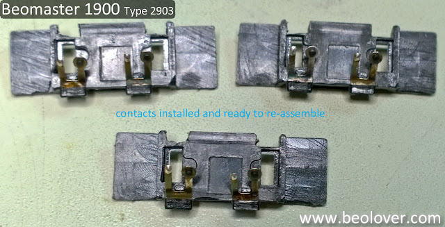
Here are the ones from this Beomaster installed in the bridges and then assembled into the slide potentiometers.


The bridges are not physically keyed so you could accidentally install them the wrong way. Make sure the bare contacts line up with the metal tracks. It is also important during the handling of the contacts to avoid disturbing the contact with the small, black coal piece.

Once the slide potentiometers are re-assembled their mounting holes to the board are keyed so the only thing to be careful with is that the 50KΩ potentiometer is placed in the Bass mounting location.


The rest of the task is just to snap and solder the potentiometers back into position on the removable board and remount it to the main board.


That is followed by a quick test play to make sure the reworked sliders function properly.


Note that I have the smoked glass display cover removed for polishing.

Saturday, May 23, 2015

Beomaster 4400: RIAA Equalization - Weak Bass

It seems that the Beomaster 4400 that I am currently restoring is now mostly working. After I bridged all the cracked traces on PCB#6 I finally had a stable Phono input and a working AFC. But then I realized that the right channel Phono input did not yield much in terms of low frequencies and was lower in overall volume compared to the left channel. The tape inputs were working, so this indicated that the RIAA equalization on that channel did not work properly. Here is the relevant part of the circuit diagram:


I added some benchmarks measured on the left channel in the diagram. Input was 10mVpp. This yielded ~3.9V at 100Hz, 900mV at 1kHz, and ~190mV at 10kHz, corresponding to an about 20x drop between 100Hz and 10kHz (=26dB). This conforms with the RIAA curve as shown here (from this very interesting article about different ways to achieve RIAA equalization - another proof that anything can become a complicated topic if one only digs deep enough...;-): 


The red curve is the one that the Phono input needs to achieve. What is coming from the record follows the green curve, i.e. low frequencies are recorded at a much lower volume than high frequencies.
The main reasons for doing this are (1) to increase the playback time and (2) to reduce high frequency noise. Lower frequencies need more space in the groove for the same amplitude output than higher frequencies. This is a consequence of the fact that the current induced in the moving coil of the cartridge is based on the speed at which the iron moves relative to the coil. If one would want to achieve low freq reproduction at the same level as high freqs, the grooves would need to be much wider, which would significantly reduce the play length. By accepting a lower amplitude for low freqs the grooves can be kept narrow and so the record plays longer.
Higher frequencies benefit from being cut at higher amplitudes since that gives a larger signal-to-noise ratio at the upper end of the spectrum. The 'natural' noise of records comes from roughness of the vinyl material, which generates a noise floor. Since during playback the RIAA curve reduces the high frequencies relative to the lower frequencies, the vinyl noise is reduced. This is a similar concept to Dolby NR where low volume sections of the recorded signal are amplified on the tape, and then reduced during playback, which also reduces the tape noise.

Anyway, anything that changes the signal depending on frequency immediately 'smells' like a capacitor issue. The two capacitors in the Phono preamp circuit that are responsible for the RIAA equalization are C105 and C104. And sure enough one of the corresponding units on the right channel circuit, C205, gave me a strange reading. My capacitance meter yielded a fluctuating signal, while C105 yielded a solid 10nF reading.
So I put in two replacements (it is best to do such things in pairs to keep the channels even). Since I did not have 2% tolerance caps available, I went through he batch I had and measured them until I found two that had the exact same value of 10.2nF, i.e were in spec. I soldered them in:


And tested the unit with a 10mV signal on both inputs. The signals were very even on both channels through the entire frequency range. Very good! I put things back together and hooked up the Beogram 4000 that I just restored, and pure bliss! I listened to Autobahn by Kraftwerk on the original German first pressing double album, and all was good! 

While I listened, I decided to explore the topic a bit more and I made a model of the Phono pre-amp in iCircuit (an absolutely great app for spontaneous circuit explorations - not as powerful as a Spice simulator, but so much more pleasant to use - give it a try: iCircuit costs less than a couple high-cal drinks at Starbucks..;-). Here is a screenshot of the model:


The simulation pretty much confirmed the measurements that I made on the 4400 unit. I rearranged the  circuit components a bit to make more clear how this RIAA equalization works.

The voltage divider at the output formed by the three 36.5, 220k, and 470 Ohm resistors and the emitter resistor R103 (330 Ohm) determine the gain of the amplifier via feedback. Without C104 and C105 the gain of the amplifier is ~460 across the entire frequency spectrum, i.e. 10mV at the input generate 4.6V at the output. The RIAA equalization is produced by adding the two capacitors that reduce the 36.5k and 220k resistor values depending on frequency. This reduces the upper end of the voltage divider more and more with increasing frequencies, hence, increasing the feedback and in consequence reducing the gain. This has the effect that the output of the amp is reduced at higher frequencies, and we get the RIAA equalization.

In this context I was wondering about the failure mode of C205. I think it must have partially short circuited the 220k resistor causing a reduction of the base gain of the amplifier. Since this affects the low end more than the high in this circuit, it appeared to the listener (me) as if the low end was missing.

Anyway, this seems to be fixed now! Kraftwerk! Autobahn!


Wir fahr'n fahr'n fahr'n auf der Autobahn
Vor uns liegt ein weites Tal

Wir fahr'n fahr'n fahr'n auf der Autobahn
Vor uns liegt ein weites Tal

Die Sonne scheint mit Glitzerstrahl
Die Fahrbahn ist ein graues Band ...


This is Beolove!