After I replaced all electrolytic capacitors a preliminary test of the Beomaster 4400 (2419) that I am currently restoring yielded that the phono input would only work intermittently. Further testing revealed that also the automatic frequency control (AFC) did not work. Furthermore, in my first happy excitement I also did not understand that the tuning lights are supposed to be off during non-FM listening, while the signal meter is supposed to be at zero. Both conditions were not met when I switched the unit to Phono.
After some measurements I figured out that the muting function, which should only operate when FM is selected and mute the tuner output in-between stations, came on intermittently, which muted the phono signal resulting in a fluctuating phono experience.
In combination with the lit tuning lights and the non-zeroed signal strength meter, this suggested that the tuner still had an issue. When I started working on this unit, the tuner did not work at all. It turned out that PCB 6 has a crack which prevented the tuning voltages to be applied to the front end. I jumpered the tuning voltage traces on this PCB and thought I was done after the tuner started working. But not so! After consulting the relevant section of the circuit diagram,

I realized that all these problems would occur if the ground connection of the preset and FM switches were disconnected (left center of diagram). This ground connection becomes active when all FM switches are in their off position. In this case, the signal strength meter ("radicator") and the power supply of the tuning lamps (blue dashed box) are turned off via D25 and D18. A look at the PCB schematics

immediately suggested that the crack in the PCB was a bit longer than I had assumed. Since this part of the board is not easily accessible I was not able to assess the damage initially. The black bar in the above picture indicates the approximate location of the crack. It disconnects the GND/black lead from the FM buttons. It is obvious that this also disconnects the AFC switch. This explained why AFC had no impact on the tuning experience (it helps to find the center of the frequency band for a station).
After I realized the extent of the damage and the number of jumpers that would be necessary to fix these issues, it was obvious that the front panel of the Beomaster needed to be removed a bit for better access to the solder points of this PCB.
So I started to disassemble. It is not too difficult an operation to pull the front plate one inch away from the main PCB. This gives enough access to allow some careful soldering activities on this board. The first step is to remove the 'slide rule'. Once it is removed the screws that hold the front panel to the enclosure can be accessed:
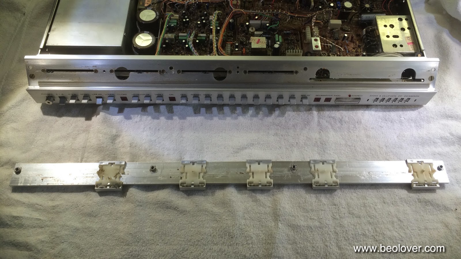
Here a detail shot of the small adjustment wheels that are in the volume and FM dial sliders. They come out easily, i.e. one should be careful when removing the slide rule to not lose them:

After that was done and the four screws were removed, the two PCB clamps (pic below shows one of them below the resistor) that hold #6 to the main PCB #5 needed to be pushed through their holes:

After that was done I carefully pried the front panel away from the main board by an inch or so to gain some access to the top of PCB #6:

The picture shows the jumpers installed (red, blue and grey). After the jumpers were in, I gave it a quick test to make sure everything was fixed. It was. So I put everything back together.
Then I hooked the Beogram 4000 up again and put one of my favorite records on: Miles Davis - In a Silent Way. I have the MoFi reissue, which sounds delicious. Unfortunately, while the muting problem was gone, I realized that the two channels were not balanced. The left channel sounded great, but the right channel had very weak bass. Only higher frequencies made it through. This indicated to me that there may be an issue in the RIAA equalization in the phono pre-amp. Oh well, back to the bench for some more testing!
No comments:
Post a Comment
Comments and suggestions are welcome!