After a little Beolover Blog posting hiatus I am ready to do a restoration project for an owner that sent me two Beomaster 1900 receivers. As a Bang & Olufsen collector that owns multiples of the same type of components I fully understand :-).
Both of these Beomaster 1900 units look to be in nice shape from the outside.
Let's dive into the first one.
As I said, the cosmetic appearance of the Beomaster 1900 is pretty good. There are some typical problems though...
Almost all of these Beomaster 1900 (and BM2400) receivers have deteriorated cabinet feet, bumper pads for the control panel lid and some peeling of veneer from the cabinet trim.
This one has issues with those three categories.
As I have installed on other Beomaster 1900/2400 projects, I have replacement cabinet feet.
For the lid bumper pads I will have to fashion new ones.
On the veneer problems I will have to glue and clamp the problem areas.
Before I start opening up the cabinet I did a quick check of powering on the Beomaster so I could see what lamps are working.
You can see that the Treble and Balance indicator lamps are not working.
So it appears that only the Treble and Balance indicator lamps are burned out.
Now to do some cabinet disassembly so I can look at what the inside condition is like.
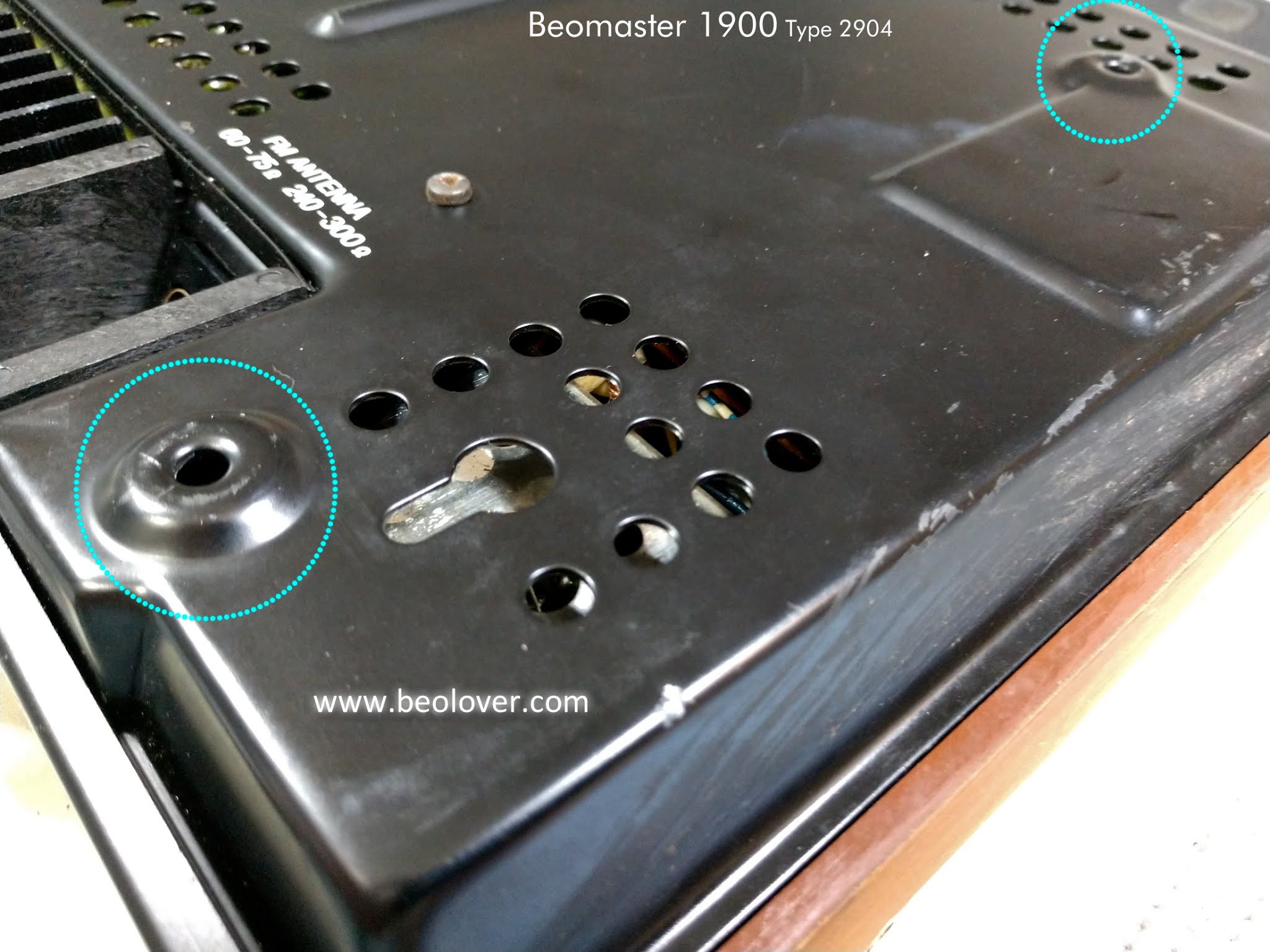
Starting with the top of the cabinet there are two screws that mount the Beomaster control panel to the frame. This photo of those two screws also shows the deteriorated lid bumper pads.
There are four screws on the rear part of the Beomaster 1900 that must be removed.
The bottom plate of the cabinet has five or six screws. I guess it depends on the serial number as the later serial number Beomaster 1900 and the Beomaster 2400 units have a long screw that mounts in the speaker/source connector cavity. Both of these early model Beomaster 1900 units do not have that screw.
This Beomaster unit's cabinet base plate is also missing one screw form the left front corner.
It does have the small, coarse threaded screw with the lock washer.
Five screws must be removed to open up the button and display panel.


The two long panel mounting screws on this early serial number Beomaster 1900 are plain, slot-head screws. Other Beomaster 1900 and 2400 units I have restored use the same brass colored, Phillips-head screws the short one in the photo. Both sides of the cabinet are like that so I assume those screws are original. The brass colored screws on the front corners of this Beomaster are missing their washers though.
With the panels off I can check the tone control and FM tuner select board that is under the control panel (and lid).
Interestingly the Bass and Treble slide controls are the type with the flat bar (for the plastic bridge with the contacts). The Balance slide control has a round metal bar for the slide.
As I understand it the style that the Balance control has was a later design that was available in the Beomaster 2400 receiver. My last Beomaster 2400 receiver project had this type of slider for all three controls. This newer slider control seems more reliable and not prone to the failure the flat slider bar controls have. I have come across Beomaster 2400 units with the flat bar style slide controls so was the Balance slider here the result of a repair?
In any case, these three controls in this Beomaster 1900 seem intact and good by my initial visual inspection. I will check them out more closely later during the restoration.
Looking at the electrical components it is visually obvious that this Beomaster is way overdue for replacement of the electrolytic capacitors.
I can see where some past repair was made to this Beomaster though. The original rectifier bridge must have burned up judging by the black residue on the main board where the original rectifier was located.
In its place is a new bridge rectifier made up of individual diode components. It works of course but I will be looking to replace it with an actual bridge rectifier, single device.
There are also at least three capacitors near the bridge rectifier that are not original. Most likely they were part of the repair needed after the original rectifier failed. It looks like good quality replacement capacitors were used.
On the underside (trace side) of the tone control and FM tuning control board I see that the board connectors are like all of the board connectors used in the early serial number Beomaster 1900 units.
They are actually small circuit boards with pins that plug into receptacles mounted on the tone control board.
No problem with those but you need to be a little more careful handling them.
The main board of this Beomaster has some resistor components mounted on the trace side of the board. I haven't seen those on the other Beomaster 1900 restorations I have done so I will check out what is going on there.
I took a peek at the Beomaster's output amplifier transistors that are mounted on the rear, chassis heat sinks. They are not dried out so that is good. However, I will be removing the heat sinks from the transistors during the recapping task so I will replace the transistor thermal insulation with SIL-Pads.
Another thing I checked was the damping grease in the hinges used by the control panel lid. This Beomaster looks like most of the grease has been removed. I will apply more as needed when I reassemble the Beomaster at the end of the restoration.
That is all I need to do for the initial assessment. Except for the new bridge rectifier I have all of the other parts I will need. Having restored quite a few Beomaster 1900 and 2400 units I keep a good supply of capacitors, trimmers and lamps.
On the next post I will do the assessment of the second Beomaster 1900 and compare its needs to this first unit.


No comments:
Post a Comment
Comments and suggestions are welcome!