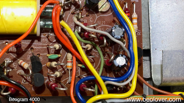
This post summarizes the work done on the Beogram 4000 that I recently received from New York (this post gives an initial assessment of the unit).
As usual I started with rebuilding the arm lowering and carriage transport mechanisms. They usually have issues due to hardened lubricants.
I extracted all the moving parts for a thorough cleaning in an ultrasonic cleaner:
While the carriage was upside down, I also extracted the corroded terminals of the solenoid activated switches. This shows the switch terminals in their original bent and oxidized condition:
I unsoldered the small boards on which the switches reside:
I also removed the carriage position indicator PCB, which also had strongly oxidized switch terminals, as well as a solenoid current limiting resistors that obviously had overheated a bit in the past, as is indicated by the blackened board beneath the resistor:
I removed all the terminals from the boards:
and plated them with Ni and then Au, the industry standard for gold plated contact terminals:
This shows the plated terminals installed back on their boards:
Very Beolovely!
While the carriage board was up it was easy to access the solenoid transistor, which I replaced with a new TIP41. It was probably the culprit for the blackened resistor, as well as the fact that this deck blew its fuses.
Once the arm lowering and carriage mechanism were put together again, I focused on restoring the electronics. This shows the original condition of the reservoir and motor capacitors and the AC motor:
Some of the capacitors had leaked already, as was evident from such 'blooms' growing from their seams:
After removal of all the components from this section, the extent of the leakage was apparent (such residue can be cleaned by soaking it for a couple hours with an alcohol drenched paper towel):
This shows the main PCB in its original condition
and the power supply board:
I took the AC motor apart for an oil bath under vacuum:
This shows the 'enclosure can' halves submerged in oil. This usually cures any knocking issues that remain after adjusting the motor voltage:
This shows the motor reassembled with my 3D printed 'brackets' that replace the original rivets that had to be drilled out for access:
This shows the main PCB after replacing all the electrolytic capacitors, the RPM relay and RPM trimmers, aas well as the sensor arm transistor:
And this shows the power supply board with new electrolytic capacitors:
After restoring the boards and the motor I installed new capacitors with a 3D printed fixture that holds everything neatly in place:
Now it was time to rebuild the keypad cluster, which can be removed from the enclosure due to its long cable harness. Of course the strobe mirror had come off:
I opened up the clamshell style electronics, revealing the logic ICs and the position indicator and RPM trimmer illumination bulbs:
The contact terminals that are actuated by the keypad keys were also oxidized:
I removed them
and gave them the gold plating treatment:
Then I reinstalled them:
The next step was to replace the light bulbs with LEDs. This shows the original bulbs:
and their LED replacements:
This shows the scale illumination LED boards in action together with the 33 RPM trimmer illumination LED:
The I glued the mirror back into place with epoxy:
This concluded my restoration of the keypad cluster. The next step was restoring the broken MMC cartridge tab. This is a frequent issue with the 4000, since the plastic they used becomes brittle over time:
This can be fixed by implementing a 3D printed replica design in combination with cartridge contacts made from flexible PCB (also gold plated):
This shows the entire arm insert consisting of my replica part with the tab that holds the cartridge, assembled with the surviving original components that carry the grounding tab for the cartridge housing, as well as the back contacts that make contact with the PCB that is in the back of the arm:
This shows the insert installed in the arm. Looks like new!
I moved on to the sensor arm, which had a broken off bulb. I replaced it with a flex-PCB based LED replacement circuit, that simulates the current draw of the light bulb:
This shows the flex board folded into the small bulb compartment:
Now it was time to upgrade the signal path. This shows the original corroded DIN5 connector:
and its replacement with a nice modern all metal unit with gold plated contacts:
I also installed a grounding switch, that allows connecting system and signal grounds. This can be very helpful if there is a hum related to grounding loops between the Beogram and the amplifier:
This concluded the restoration of the electronics and mechanical parts. I moved on to the more cosmetic part of the restoration. As usual some of the plinth guidance washers were cracked:
I replaced them with 3D printed parts. One of them is black, to be used for the front-center washer, that is is not visible through the crack between aluminum plate and plinth:
This shows one of them installed (under the keypad):
The next step was repairing the cracked hood hinges. This shows one of them with the typical fracture around the screw holes where the hinge is bolted to the hood. This area sees the highest stresses and is weakest due to the holes.
A while ago I came up with a method for stabilizing such cracks by gluing thin patches onto both sides of the cracked areas.
The patches can be clamped with 3D printed parts that fit exactly to the mounting holes:
After 24 hours of hardening it was time to take the clamps off and remove the carrier plates that hold the patches in place during the attachment process. This revealed the patches and clogged up screw holes (the clamps cause some of the dissolved plexiglass to squish out from between the patch and the hood). I usually use a countersink to open up the countersinks for the screw heads,
followed by a 3.5 mm drill to open up the holes:
And this shows the final result:
The next step was polishing the hood. It had the usual scratches from cleaning with too harsh cloths and storage. I bolted in the hinge to stabilize the hood sides and gave it a couple hours on my work bench in the garage, where I first equalized the scratches with some 320 grit sand paper. And then I polished it back to translucency with about 8 steps of ever finer sand paper. Once that was done, it was time to apply a new aluminum trim. For this I protected the polished hood with a plastic bag and some blue tape:
Then I applied contact cement to the trim recess on the hood and the new trim. After 10 min of letting the glue dry I pressed the trim into place, and that is the final result:
Of course I also installed new rubber bumpers to give this hood the solid 'plonk' it deserves when being closed. The original bumpers are usually corroded away and broken off:
I usually install short pieces of a 2 mm O-ring and cut them to 1 mm length
Before doing the final adjustments I replaced the original tracking sensor light bulb with a LED based assembly that has an added intensity adjust. This allows fine-tuning the tracking response after doing the basic adjustment. This shows the original and new tracking sensor light sources in comparison:
And after implantation:
At this point I also replaced the original cracked carriage pulley with a new precision machined aluminum part and a new belt:
After this I adjusted the floating chassis and the platter to be parallel with the arms and the aluminum plates. While this can be said in one sentence, I usually spend about 2 hours on this adjustment since it is a bit (to paraphrase Scotty's description of trans warp beaming...) like trying to hit a bullet with a smaller bullet whilst wearing a blindfold, riding a horse...;-).
And then it was time to get some electricity into the deck. It came with a cutoff power plug, i.e. I had to install a new one:
I also installed two new fuses, since the original ones had blown before I received the unit. Since this was the case, I initially ramped the voltage up with a variac, but the fuses held and there was no excess current indicated. This meant that I apparently fixed the issue that blew the fuses by replacing all the 'known culprits' during my restoration.
With the unit powered up, it was time to do a few adjustments. First I adjusted the motor voltage. I usually go as high as possible without getting significant distortions in the sine wave that goes into the motor coils (if the motor knocks a bit, reduce the voltage a little, that often takes care of it):
Then I adjusted the bias of the sensor transistor TR14 to get about 1.8V on its collector.
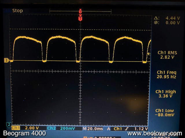
Then it was time to measure the sensor response at the TR14 collector. This is the signal I got with the platter moving under the sensor:
A nice strong signal with all the valleys going down to 0V. As it should be! After this measurement I moved the bias trimmer to the component side of the main PCB.
The next step was to adjust the tracking feedback:
And the arm lowering limit. This is an important adjustment since it can prevent tip damage if the system accidentally would lower the arm on an empty platter:
Then I calibrated and adjusted the tracking force:
And finally I did a 24 hrs RPM stability test. This is not really necessary with the AC motors since they usually run extremely stable, but it is always nice to see the curve. This shows the BeoloverRPM device that allows logging the RPM in 10s intervals over extended periods of time:
And this shows the nice curve I measured:
I also calibrated the 45 RPM setting:
After this I gave the aluminum surfaces a deep clean, and put everything together.
And finally it was time for a first spin. I am currently enjoying a bit of a Modern Jazz Quartet 'episode' and so I put on one of my favorite of their compilation albums "The Modern Jazz Quartet Plays for Lovers" (Prestige PR 7421 from 1965). Of course, this vintage album was ultrasonically cleaned on a CleanerVinyl Pro System, which restored it to a pristine state with very few clicks and pops!
Quite beautiful! I will now play this deck for a couple more weeks to see if everything is stable, and then it will be time for it to return to New York to its owner!


No comments:
Post a Comment
Comments and suggestions are welcome!