I recently received the DC platter motor, both PCBs and the RPM panel from a Beogram 4002 (5513) in California. As usual I started with the motor since it can take a few days until the oil infusion of the bearings is complete. This shows the motor as received:

I disassembled it to get the bearings out:

Then I immersed the bearings in motor oil and pulled a vacuum:

Immediately vigorous bubbling started, indicating that air was drawn out from the porous bearing material to make room for oil inter-diffusion. While the infusion was in process I focused on the remaining parts.
This shows the main PCB in its original condition:
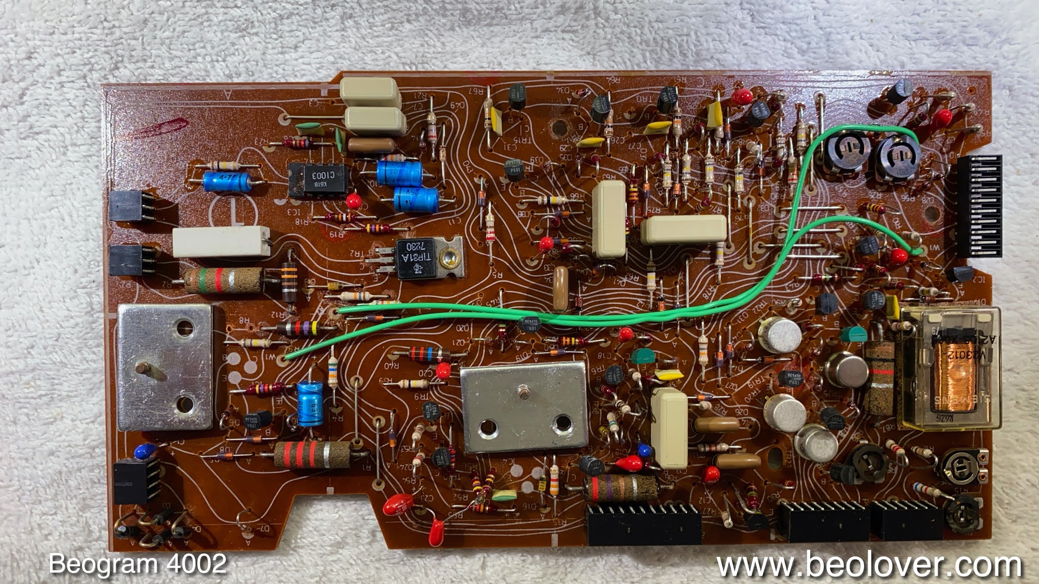
A detail shot of the 'RPM section', consisting of two RPM trimmers and the original Siemens 33/45 switch relay:

This shows the original setup of the sensor arm amplifier. Replacing the transistor and installing a trimmer for adjusting its bias precisely should be part of any Beogram 4002 restoration:

This shows the board after rebuilding it:
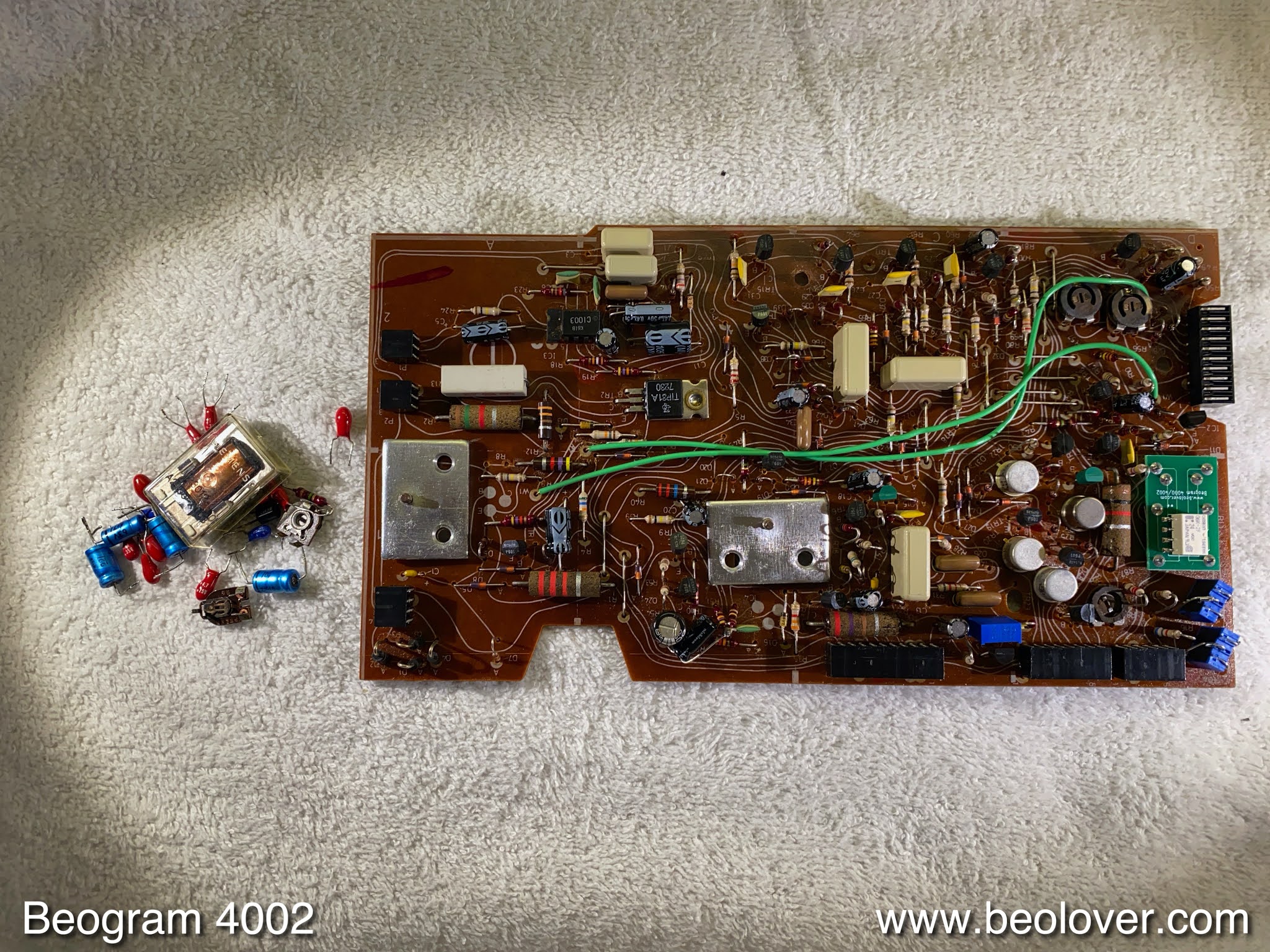
A detail shot of the renewed RPM circuit:

and the sensor amplifier. The blue 'box' is a 25-turn precision trimmer to adjust the bias of the transistor.

The next step was to rebuild the output board. This shows it in original condition:

I replaced the output relay (it grounds the signal leads until the needle has safely landed on the platter), installed a switch that allows connecting system and signal grounds (this usually cures humming issues with RCA based amplifiers), and I replaced the capacitor that defines the time constant of the relay action during arm lowering:

The final part of this project was to replace the incandescent bulbs of the RPM panel. This shows it as received. One bulb cover appears to have gone missing, revealing one of the bulbs:

This are the LED boards before installation:

I put them in

and replaced the covers. Luckily I still had a spare cover:

then it was time to finish up by adjusting the sensor arm transistor bias to get 4V at its collector.

After this was done I verified that the sensor signal was according to specifications. This shows the signal as measured with a rotating empty platter under the sensor:

Whenever a black rib passes under the sensor, the signal goes down to 0V. This signal looks very good. The final step was to put the DC motor back together, calibrate 33 and 45 RPM and then measure a RPM stability curve over 24 hrs with the BeoloverRPM device:

This is the curve I measured:

This is as good as it gets with the DC motor Beogram 4002. These parts are ready for for duty again and will soon be sent back to California!
No comments:
Post a Comment
Comments and suggestions are welcome!