I completed the Beogram 4000 restoration that I started a few weeks ago. Check out the starting point here. This post summarizes the 'functional restoration' tasks. I already made a few detail posts about the work done on the plinth and the hood, and fixing a strange issue where the solenoid would briefly activate when "ON" was pressed, right at the moment the carriage would start moving towards the platter.
I start most 400x restorations with an overhaul of the carriage and arm lowering mechanisms. They usually have hardened lubricants that impede motion. This shows the carriage removed from its rods and spindle:

I disassembled the arm lowering mechanism and cleaned and re-lubricated all components:

And did the same with the rods and nylon fixtures that interact with them:

The next step was to extract the damper to arm linkage from the sensor arm:

I cleaned and re-lubricated the pivot point, which is often trouble source, and put the mechanism back together:

After this operation I installed the sensor arm back in its place and adjusted the arms to be parallel:

I also replaced the cracked original plastic pulley with a nice new precision machined aluminum pulley. I get them from an enthusiast in Vienna, who has them machined in a local shop. I'll be happy to get you in touch if you wanted to get one. They make the carriage run much more quietly compared to the old wobbly plastic pulleys. Beolovely!

My next focus was restoring the PCBs. This meant replacing all the electrolytic capacitors with new 105C types, and replacing the RPM relay and the RPM trimmers:

This shows the 'RPM section' in detail.

The new 25 turn RPM trimmers were installed that their adjustment screws are accessible from the solder side of the board:

I also replaced the two electrolytic capacitors on the power supply board:

Then it was time to tackle the 'big can section' where the motor and reservoir capacitors are clustered together around the AC platter motor:

I removed all the original capacitors, some of which were leaky (they often are at this point in time):

I also took out the motor for an oil immersion:

This requires the removal of the four threaded rivets. I usually drill them out on a drill press:

Once this is completed the sturdy can-motor design pops open,

and the two can halves can be immersed in oil under a vacuum:

I usually do this for ~24 hrs. This process reliably stops any knocking that these motors can be prone of due to their tractor like torque, which does not react kindly to friction in the bearings. Since the rivets are 'gone' after this process, I designed 3D printed 'nut holders' that fix the nuts in place below the rivet holes, which allows bolting the motor back into its compartment, and adjusting its tilt relative to the belt plane:

This shows the motor and the new capacitors installed:

The motor and reservoir capacitors are held in place with a 3D printed fixture that creates a clean setup with the modern, and therefore much smaller replacements.
The next step was rebuilding the keypad cluster, which houses the logic circuit of the command center of the turntable aside from light bulbs that illuminate the position scale and the user accessible pitch trimmers for 33 and 45 RPM. The keypad is held in place with a single screw at its back end. After removal the pad can be extracted. It is connected with a fairly long wire harness:

I put the PCBs into their service position. The nearly blackened strongly oxidized contact tabs of the keypad switches are visible on the lower PCB:

These switches are one of the main sources of trouble in the Beogram 4000. I usually plate them with gold to prevent future oxidation. For this process one has to extract all of them. A de-solder gun is essential for this process:

This shows the tabs after plating with Ni and cobalt alloyed 24 carat gold, which is the standard for PCB connections (the added Co creates a harder coating, making it more resilient to mechanical stresses):

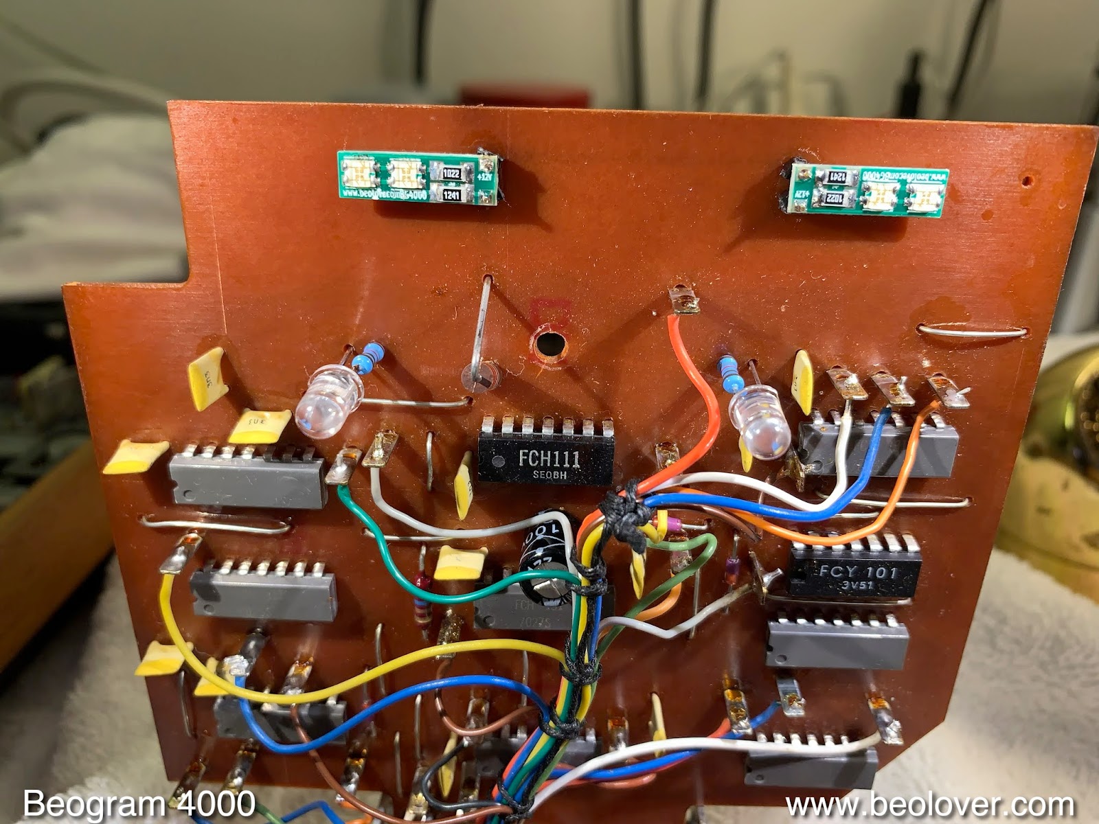
Ah the sheen of gold! Beolovely! On to replacing the four light bulbs on the upper PCB. I replaced them with my specially designed LED boards for the scale illumination, and with two standard red LEDs for the RPM trimmer back illumination:
As usual the strobe mirror fell off due to degraded glue:

I epoxied it back on:

Then I put the keypad back together and focused on gold plating the remaining mechanical switches. A lot of functional issues are usually related to the 'solenoid activated switches', which are a bit difficult to extract since there are many thin wires attached around them that can be wiped off very easily. I removed the three small PCBs with the solenoid current limiter switch, the output grounding switches, and the tracking enable switch. All three were 'nicely' corroded and also bend, due to earlier attempts at restoring functionality, probably after one or more of the switches failed due to oxidation:

I removed the contact tabs

I plated them together with the tabs of another five switches from underneath the carriage (they tell the control system where the carriage is located at a given point):

Then I reassembled the switches

and reinstalled everything.
The remaining incandescent bulb to replace was the sensor arm bulb for the record detection mechanism. This Beogram still had the original 'slide out' fixture, which makes it straight forward to replace the bulb with my LED flex-PCB circuit:

This shows the flex PCB folded into the bulb cavity. The circuit contains a current bypass ensuring enough current flow parallel to the frugal LED to convince the control system that there is an operating light source in the sensor arm:

After I installed the LED replacement I measured the sensor signal and it came out to be too low. This is usually caused by a transistor that has lost some of its original gain.

I replaced it with a modern high gain type and installed a 25-turn trimmer to be able to accurately adjust its base bias. The collector voltage should be about 1.8V after this adjustment:

After adjusting the trimmer, I placed it 'below deck' on the component side. It needs to be put in flat, since there is not much space between the board and the suspended chassis:

After this procedure all was well and a proper ~6V amplitude was achieved. This shows the LED in action. Due to its 'warm white' characteristic it is able to properly illuminate the red B&O logo, like an incandescent bulb would:

After this last upgrade it was time to do the adjustments. I adjusted the floating chassis to be horizontal and the platter to be flush with the aluminum panels. Another focus of these alignments is to get the arms parallel to the platter and at the right distance. Once that was done, I adjusted the arm lowering limit high enough that the needle would miss the platter ribs should there ever be a malfunction of the record detection system:

Then I calibrated the tracking weight of the tonearm. I locked the position of the counterweight in place by replacing the original circlip with a nut that allows tightening against the adjustment screw. This is essential if the turntable is to be shipped while maintaining its calibration:

Then I calibrated the scale of the weight adjusting wheel to yield 1.2 g at its 1.2 g setting. This scale is notoriously imprecise, i.e. I try to make it match the actual weight at the setting that most likely is used for most B&O cartridges:
Then I adjusted the tracking feedback to specification
And finally, I set the motor AC amplitude to the correct value at 33 RPM (~5-6Vrms).

45 is always about 1Vrms lower, but there is no way to adjust it separately.

Finally, I calibrated the RPM with my BeoloverRPM device, which counts the number of ribs per time and determines the speed from that:

The last task before putting on the first record for a test spin was to update the signal path with a grounding switch, that allows connecting system and signal grounds in case there is a hum issue,

and by replacing the corroded standard DIN5 plug with a gold plated all metal modern plug. This shows the blackened pins of the original plug:

I cut it off, and prepared the wires for the new plug:

Then I soldered it on

and here is the lovely result. Golden!

And then it was finally time for a test drive. I selected a recent addition to my ever expanding collection, "Call" by the Martin Naura Quartet. This album is one of my all-time favorites. A 1971 recording for MPS Recordings (CRM 877) that was far ahead of its time. The quartet features Martin Naura on the (electric) piano, Wolfgang Schlüter on the vibraphone, Eberhard Weber on bass, and Joe Nay on the drums. I bought a recent 180g audiophile re-release which is of superb quality. Before playing it it was ultrasonically cleaned with a CleanerVinyl Pro System on an Elmasonic P60H dual frequency cleaner at 80 kHz to get rid of the pressing release agents. The record has no clicks and pops whatsoever, and a really nice roomy sound.

I hope they will finally also re-release the beautiful and hard to find sister album "Rainbow Runner" from 1972 on the German Spiegelei ('fried egg'...;-) Label (28 522-1 U).
I will now play this Beogram 4000 for another 1-2 weeks and then it will be time for its trip home to Michigan!
No comments:
Post a Comment
Comments and suggestions are welcome!