There are two of these output amplifier assemblies in a Beomaster 8000. One for each channel. Only one of the amplifier channels is giving him a problem so he sent the bad actor to me.
Here is the output amplifier assembly as I received it. The heatsink components all look good but the amplifier board has problems with failing component solder pads. They have likely been over-heated and have released from the board. The owner attempted to repair them but I found problems with those.


The electrolytic capacitors have already been replaced as well as the two 100Ω trimmer resistors for the no-load current and DC offset adjustments.
I prefer multi-turn trimmers for this board though so I will replace the installed single turn trimmers. I will also de-solder the components associated with the failed solder pads and make repairs to those.
Here is a closer look at the trace side of the board with the problems.


The worst section of the damage is the broken solder pad for the positive lead of capacitor 5C211 (100uF, 16V). Examining the traces for that capacitor I see that it can be remounted across two of the solder pads for the 5R200 (DC Offset) trimmer...which I am replacing anyway.
I installed a smaller, radial type electrolytic capacitor for 5C211 and it fit very nicely.
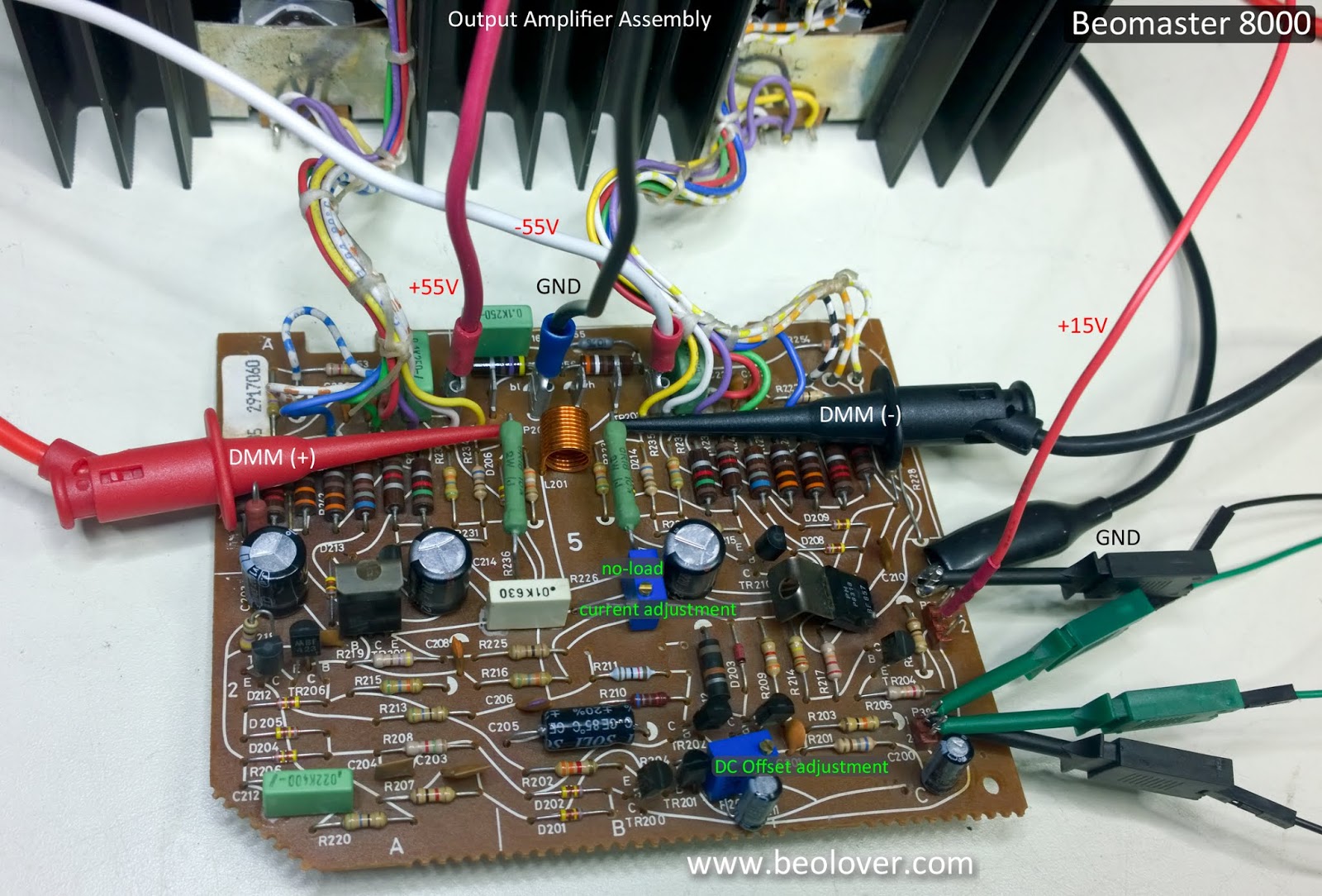
Here are pictures of the reworked amplifier board.

Capacitors 5C202 and 5C215 each had a broken solder pad so I routed their connection paths using the purple colored wire shown in the picture below.


This board is ready for bench testing where I will make the no-load current adjustment and the DC offset adjustment.
The first step of bench testing is to reset and check that my bench DC power supplies (that will provide the ±55VDC rail voltages) are correctly set to a current limit of 0.15A. That will protect the board (and me).
After the current limits have been set on the power supplies I can connect up the power and ground wires to the output amplifier board for testing.

Next I apply the ±55VDC rail voltages. The output amplifier will not fully be on until I the +15V supply is applied to the amplifier. Here is what the power supplies should look like at this point.

This is a great sign. So far so good. The output amplifier is essentially in standby mode and only drawing 30mA from each rail.
Now I turn the amplifier on by dialing up the +15V supply. I do this a little bit at a time. I don't jump right to +15VDC. Because the no-load current trimmer has been replaced, I don't know where the initial setting needs to be.
As I start applying voltage to the +15V supply line the current draw on the ±55V supplies starts to go up. I don't want that current to go higher than 100mA to 110mA (on each supply). Of course I have the current limit on the supplies set to 0.15A as a backup so no real worries.
In this case I reached 110mA when there was only +6VDC on the +15V supply. The voltage across the two emitter resistors was 24mV.
I turned the no-load trimmer resistor so the current draw on the ±55V supplies dropped back down to around 60mA. Then I increased the +15V supply some more. That iteration continued until I reached +15VDC on the +15V supply and the current draw on the ±55V rail supplies was 100mA to 110mA.
I knew what values to expect here from having bench tested a lot of these amplifiers now.
The DC voltage across the emitter resistors was now very close to the desired 18mV per the service manual. I adjusted the no-load trimmer at this point to get as close to 18mV across the emitter resistors as I could.


One service manual adjustment down and one to go.
The next adjustment is the DC offset.
For the DC offset adjustment I turned off the bench power supplies and I connected up one of my 8Ω dummy speaker loads. Then I reapplied the ±55VDC rail voltages and the +15V supply voltage.
The output amplifier was on again and I could measure the DC voltage across the 8Ω speaker load.

Initially the DC voltage was a little high, about 0.8mV, so I used the DC offset 100Ω trimmer resistor to dial in around 0.1mVDC of offset. The service manual calls for less that 5mV so this is quite satisfactory.

This output amplifier assembly is ready to rejoin its Beomaster 8000 components and will hopefully be playing music again soon.
No comments:
Post a Comment
Comments and suggestions are welcome!