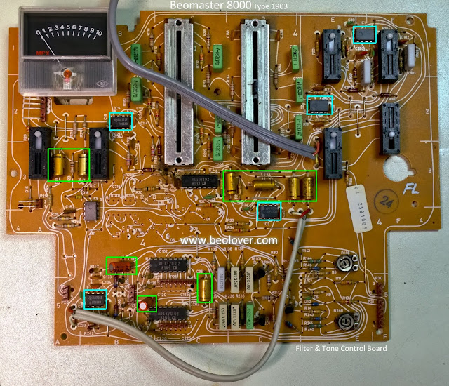
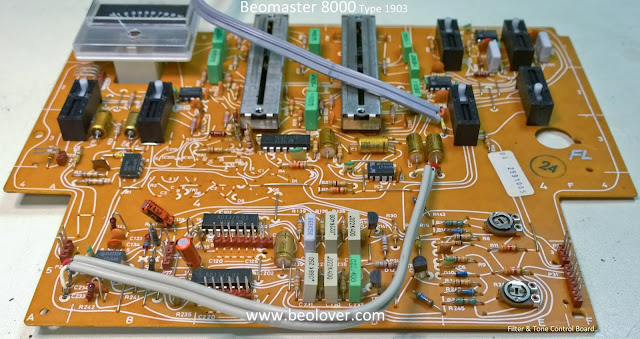
Here is the board before the restoration work.
The trace side of the board has screws for securing the filter & tone control plastic panel. This board was missing one mounting screw so I will supply one when I reassemble the board.
Here is the board with the control panel removed. The restoration will involve reflowing the solder connections of the board connectors, replacing the electrolytic capacitors, replacing the LF353N opamps and cleaning the bass/treble slider controls.
Here is the board after cleaning, reflowing, recapping and new LF353N devices.
There is an adjustment procedure in the service manual regarding the left and right channel DC offset for the Beomaster 8000 volume control circuit. If the offset voltage is too high it will result in a static or clicking noise in the speakers when the volume is changing (up or down). The two trimmers on the filter and tone control board are for adjusting out that offset. There are some associated fixed resistors next to the trimmers that can be disconnected as needed to aid in the offset trimming. The board above has two of those resistors (one in each channel) disconnected. Once the Beomaster restoration is complete I will go through the volume DC offset procedure and readjust the trimmers as necessary. I have found they usually do require some sort of adjusting.


No comments:
Post a Comment
Comments and suggestions are welcome!