UPDATE at the end of this post
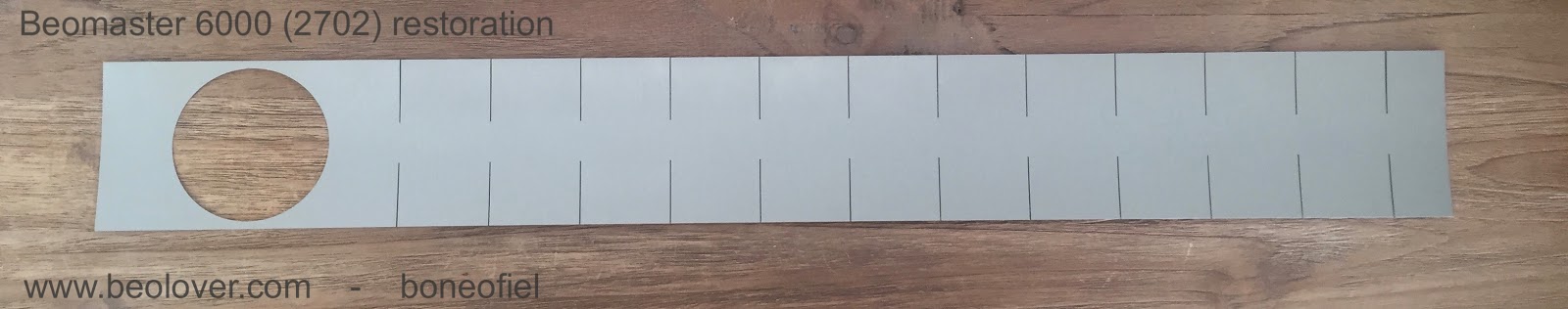
The key panel of the Beomaster 6000 quad is an interesting design that can also be found on the Beogram 4002/4004/6000 (not on the BG4000), the Beocord 5000 (type 47XX) and even to a certain extent, on the Beomaster Commander.
Little information is available on the construction of this key panel, so I made a small drawing of all the elements that make up this key panel.
The actual contact is made by pushing on the metal "tongues". Under these tongues is a locking plate (in black plastic) that is glued under the key panel. This locking plate then pushes the small purple plunger against a copper plate that makes electric contact with the copper bridge in the switch. Quite a long journey to make a contact !!
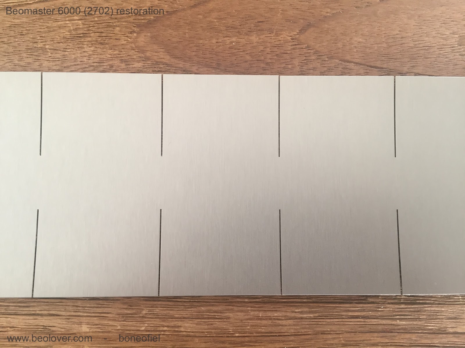
The metal key panel is made of stainless steel spring steel. It is brushed on one side (the visible side) in an industrial way with stainless steel brush rollers with a grid of 400-600. I have tried to replicate this brushed aspect on another key panel that had been sanded by someone, but did not succeed. It is impossible to get perfect straight brushed lines into the metal without using the proper industrial equipment.
The steel plate is also coated on top to give it a more satin/matt aspect in stead of the bright shiny steel. This coating is often gone on the keys that are mostly used. That creates the typical finger prints that are seen. The grease of the skin affects the coating over time.
It is also interesting to see that the steel plate tends to bend upwards if the glue is dried up after several decades and releases the steel plate. There is reason for this! The steel plate is made out of a flat piece of metal, but is then rolled to get a certain curve (see picture). This is done to create a pre-tension on the "tongues" and to make sure that the locking plates firmly touch the underside of the aluminium frame in rest. By doing this, the tongues should be perfectly flat with the rest of the panel and it also assures that no false contact is made in the electric switches.

After this rather long explanation, let's start to take the panel apart. First thing to do is to remove the locking plates. If not, you can not remove the key panel from the frame. On this particular unit, the locking plates were not only glued to the steel plate but some epoxy glue was added to make sure they stay in place. In fact, it's not a bad idea to do this since I recently got a restored Beomaster 6000 back in my work shop for a repair after a damage caused by a power spike. I noted 2 of the locking plates falling of again.
Anyhow, I had to remove the epoxy glue first from all of the 20 locking plates:
After this, the best way to remove the locking plates completely is by given them a short, firm knock with a hammer using a piece of wood. If you try to prime them off (like with a screwdriver), there is a high risk that you damage the key panel. It leaves marks on the top, visible, side of the panel.
The locking plates always have there small pieces of plastic still attached from the injection machine tools. Not really Beolove.....So, I always cut those pieces of.
Once all the locking plates are removed, it's time to get the steel plate detached from the aluminium frame. Most of the time, this is fairly easy done since the glue used at the time did not hold very well. I use a long cutter knife that I stick between the plate and frame. On the Beograms and certainly on the Beocords they seem to have used another type of glue that holds very well (and very difficult to remove...!).
The hardest part is now to get all the old glue removed. I use a flat cutter knife again and some fine grid sandpaper. Followed by an alcohol cleaning.
The most difficult part is coming up now: to get the key panel recoated! As mentioned, the panel is brushed with some coating on top. Those fingerprints are in fact areas where the coating has disappeared over time. Small scratches in the coating do not leave permanent marks. Once the metal itself has scratches, they can not be removed. DO NOT TRY TO SAND THE PANEL. It will ruin the brushed, matt aspect forever....
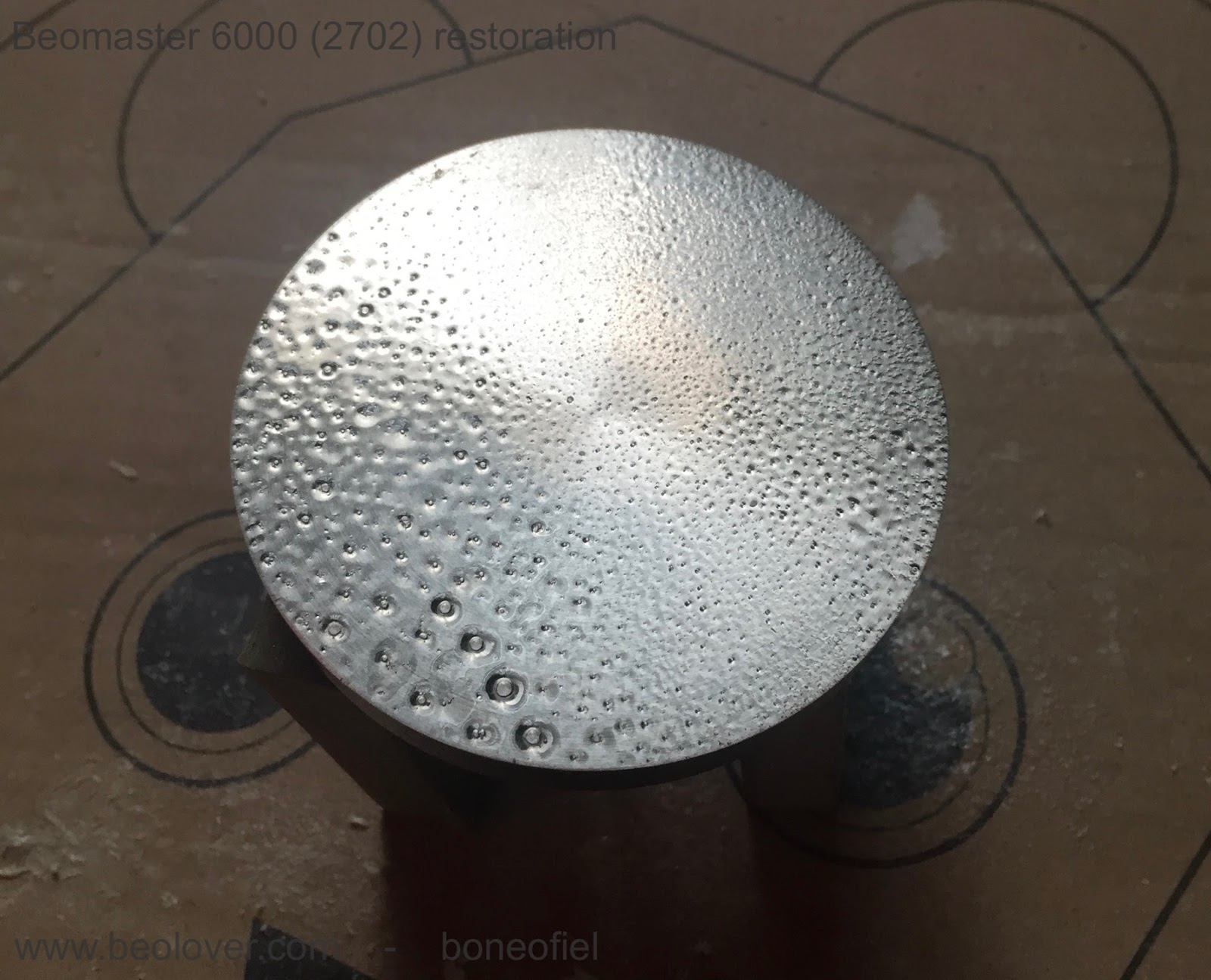
So, let's remove the coating. A special paint removal (used in the automotive industry) is used.
I always need to apply a few layers of paint removal before all the coating is gone. The chemicals used in the paint removal are dangerous, so take the necessary precautions. They act very fast (10- 30 seconds). A good wash with water and detergent is next. And yes, they shine now........and that is not the way we want it!
We need to bring back the coating. Another difficult task. I've tried different coatings/lackers and again the best is matt/satin clear lacker used in the automotive industry. You need a dust free environment to apply the coating. I looked at how spraying cabins for cars are made and created my own, miniature spraying cabin. It's made out of wood, with a plexi hinged door and a Durst UT100 on top. This Durst is used by analog film photographers to dry there rolls of film pelicule. It has a blower, a heater (with 2 settings) and a dust filter build in. It blows into the cabinet providing a small overpressure with the idea to keep dust out.
It works fairly well, but still not easy to keep all dust particle out.
Applying the coating requires some experience. I have done this like 8 times now, and still make mistakes. This time I put to much coating on the plate the first time and had to redo the procedure of cleaning and coating all over again.
The coating also requires 24 hours of hardening. I keep the heater on during the first couple of hours on setting 1 (about 40 degr. Celcius).
This is the result once the whole proces is done. The matt, satin look is back again !
Not bad at all I must say !
Back to the aluminum frame now. Once all the glue is removed from the aluminum frame, it's time to get the black lines repainted on the frame. Some masking tape is used and a fine brush to paint the lines back with matt black metal paint.
This looks a lot better already !
Once the frame is cleaned and the lines repainted, the steel panel plate needs to be glued back on the frame. To make sure that both pieces are perfectly aligned, I made a wood fitting piece. It's important that the gap (1mm) between the key "tongues" and the aluminium frame is correct and the same all along the frame. I use 4 metal plates of exactly 1mm thick as chims.
With the two pieces well aligned and the glue added, I use a wood plank and spanners to hold everything together until the glue has dried.
While waiting for the glue to dry, I took the FM dial wheel/flywheel spindle through the same procedure.
And 24 hours later, time to check all is OK...
Looks like new (well, almost...)!
All the black plastic locking plates are back in place as well.
And a few more close-ups
We are now getting really close to the finish of this Beomaster 6000 quad restoration. In my next post I'll explain the polishing of the red plexi display panel.
UPDATE !
When I started to put the keypanel back on the Beomaster, I noticed that the coated surface had a tiny mark on it. This was caused by accidentally touching the surface with glue residue left on my fingers. After doing some further testing I realised that the coating was not very durable. It looked great, but would probably show marks again after some time. This was not to my liking. So I decided to take the keypanel apart again and started to investigate more on the different type of coatings that are available on the market.
First note: the coating that I used so far is a 1K coating (1 component). 2K coatings are more durable since they have a separate hardener that is only activated just before spraying. This, according to my research, is more professional and should give a much more durable coating. My eye's fell on SprayMax 2K clear coat, matt finish. It's hard to find this product in Europe, but finally got a can. The can has 2 compartments: the top with the clear coat and a bottom one with the hardener. The latter is activated by pushing a red button that releases the hardener in the top can. After a good shake, it is ready for use. The disadvantage of this concept is that, once you activate the hardener, you have to finish the can within 24h (depending on the storage temperature).
Another modification I made was in the spray cabin. In stead of laying the panel flat, I mounted it on a stand to keep it vertical. This gives a lot less issues with dust particles settling on the surface (seems logical; why did I not think of this before...). I also raised the temperature of the spray cabin to 60°C after spraying. The SprayMax cures within 10 min, is dust dry in 30 min and touch dry in about 45 min. The full hardening process takes 24 hours however (at room temperature).
The result was looking as good as my first coatings with the 1K product. I also made a few tests on a spare Beocord key panel (same concept as the Beomaster) and after 24 hours the coating was really very hard.
This is the end result. Hard to see the difference versus the early coatings earlier in this post. The thickness of the coating is probably a bit higher since I did 2 layers of coating. This was recommended by the manufacturer and was also needed since I did the spraying on a vertical surface. If you spray a single layer to thick, you risk having sagging.
I also coated the spindle off course. Now it's time to glue it back to the aluminium frame.
This was a little set back, but the aim (remember the title of the first post...) is to get things as perfect as possible !