Featured Post

Beolover SyncDrive: DC Platter Motor Replacement for Beogram 4002 and 4004 (Type 551x and 552x)

Late Beogram 4002 and the 4004 (Types 551x and 552x), which have DC platter motors instead of the earlier synchronous AC motors usually suff...

Showing posts with label Beolover 3D printed parts. Show all posts

Sunday, January 27, 2019

Beomaster 8000 From Canada: Taking care of some loose ends before shipping home

The Beomaster 8000 receiver from Canada that I blogged about here has been undergoing extensive testing in my listening room.  The input sources (FM, phono, tape 1 and tape 2) have been exercised for countless hours. This unit has performed great.

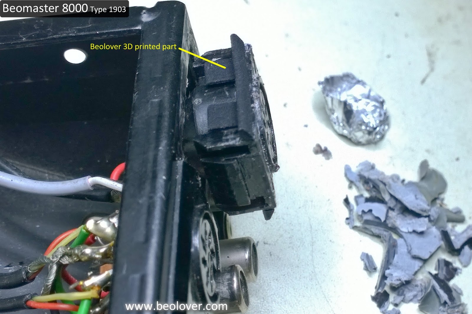
When it was time to unplug the Beomaster from my Beosystem 8000 listening room setup I got a surprise when I unplugged the Beogram 8000 cable. The Beomaster 8000 Phono DIN jack came out with. Part way anyways. The wires in the Beomaster source input connector box kept the DIN jack from getting too far.

I hadn't noticed any problem with the Phono DIN jack previously but now that is was out I could see that one tab (of two) that prevents the DIN jack from pressing into the connector box was broken and both side tabs, that keep the DIN jack from pulling out, were broken.

Here are the pictures.


Fortunately for this type of problem Beolover makes a 3D printed repair kit.


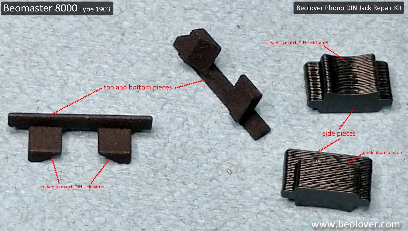
I had used the 3D printed parts for the top and bottom edges of the phono DIN jack on the Beomaster 8000 from Texas.  That DIN jack had intact side clips though so the top and bottom Beolover parts were all that were needed on that project.

This Beomaster 8000 phono DIN jack had its bottom tab intact but was missing the top one. In addition, both the left and right side clips were broken.

The next two pictures show the installation of the phono DIN jack left side stop piece. The original side clips were a flexible, spring like plastic tab. A replacement part that works as a spring clip isn't really an option. Beolover came up with side pieces that glue to the DIN jack housing in such a way that the DIN jack cannot be pulled out (the top and bottom replacement pieces are designed to not let the DIN jack press down into the connector box).


Note that just one side (the left side) was installed first. Since this DIN jack still had its original bottom tab I only needed one of the Beolover parts for that part of the assembly.

With the left side stop piece glued in place and the top Beolover replacement part installed I was able to push the phono DIN jack back into the source input box.

The final step was to glue in the right side stop piece.


The phono DIN jack was now securely mounted where it will no longer fall in or pull out of the source input box.

Here is the completed repair.


Now back to another round of listening tests before the packing up for shipment back to Canada.
That step cannot be skipped. Whenever working with the source input connectors it is really easy for one of the small wires to break.  I do not want to risk shipping this Beomaster back to Canada only to discover there is some problem I could have easily caught with a little more testing.

Thursday, November 22, 2018

Texas Beomaster 8000: Input source panel repair

When I first received this Beomaster 8000 unit from its Texas owner I noticed that the input source panel had a rather crude repair.


Yuck! Actually I understand why this type of repair was done and it actually works. But it is just so unsightly that it makes it wrong.

Fortunately the there is a Beolover 3D printed part fix for this type of problem. Installing the 3D printed parts is quite easy but the preparation to apply them here took quite a bit of work.

The first step is to remove the epoxy glue. I used some heat from a heat gun and various size razor knives to remove the glue. To protect the plastic DIN jack housing I used tin foil.


The heat did most of the work and I got all of the glue removed.
Now to apply the Beolover 3D parts. They fit perfectly into slots already there on the DIN jack housing.  No glue is necessary.


I figured that all of the rough handling by the glue removal procedure might cause some DIN jack wiring to break and that was the case.


The resulting wire repair task wasn't too bad. I just had to be careful in removing old solder connections and rewiring the broken leads.


The wires all look correct again. I checked them against a known, good spare panel that I have.

I will touch up the scratches on the metal panel with some black paint then reinstall the source panel in the Beomaster.


Monday, September 10, 2018

Canada Beomaster 8000: Changing the reservoir capacitors and some rust (?)

After an unscheduled little break over the Labor Day holiday it is time to get cracking on these Beomaster 8000 restorations.

This weekend I started on the Beomaster 8000 from Canada, replacing the four 10,000uF reservoir capacitors. These are the reservoirs for the left and right channel ±55V rails.


Starting with the left channel


The solder posts on the replacement capacitors are just a small post and do not provide the nice mounting terminal the original reservoir capacitors had.


To compensate I add a small, flat terminal at each end of the connecting bus-bar.


After that I added mounting terminals to the five wires that connect to the left channel reservoir capacitors. I won't connect those yet because I will need the slack in the wires when I reinstall the left channel output amplifier assembly.


On to the right channel reservoir capacitors.


There is the same issue with the new capacitors and mounting the bus-bar.


Solved the same way.


I went ahead and connected up the five supply wires with their new terminals on the right channel. They won't be in the way for the right channel output amplifier installation later.


I was actually hoping to reinstall the left and right channel output amplifiers after their respective reservoir capacitors were replaced. However, when working on the left channel reservoir capacitors I noticed something odd on the cabinet base that looked like corrosion.

So I took a little detour on my restoration step order.  I went ahead and removed all of the Beomaster 8000 boards from the cabinet so I could fully inspect the inside of the cabinet base.


The corrosion was rather strange. It is only on the left side of the cabinet (when looking at the Beomaster from the front). The areas with the corrosion remove the cabinet black paint when I wipe it with a paper towel.


There is no corrosion on the right side. Just some dust that needs cleaning up.


Back to the left side of the Beomaster cabinet I wiped all of the nooks and crannies that had the rust.


On this type of problem I apply three coats of a rust neutralizer. It will turn the rust black. After twenty-four hours I will check the result and see if any rust has reformed. If it does then I will retreat the areas again. Once the treatment is satisfactory I will be able to paint the inside of the cabinet with black, rust protective paint.


This detour doesn't really hold up progress on this Beomaster project. I can proceed to work on the Beomaster 8000 boards I removed.  I will return to the cabinet in twenty-four hours though to see if it is satisfactory to paint.