Today was 'switch day' for the Beogram 4000 that I am restoring right now. It is usually a good idea to clean the contacts of the many open switches in this design. I usually clean the contact areas with a 2000 grit polishing paper and then give them a coat of DeoxIT D100, which prevents further oxidation very effectively and forms a protective conductive layer. Some in the field insist that the switches need to be unsoldered and completely cleaned, but I think the risk of damaging and bending the contact tabs is too great a risk for simple cleaning. One should keep in mind that all that matters for a switch to function well are the actual areas that come into contact. So it does not matter at all if the switches look a bit dark as long as the contact areas are not oxidized. In fact it is most important that the switch tabs retain their correct shape to give the switch its correct mechanical behavior (and right feel in the case of the control panel buttons).
Here are a few pictures from cleaning the contacts of the switches on PCB7 under the carriage mechanism:
The pic below shows PCB 7 as it is installed. The switch trigger plate is already taken out for access. A while ago I made a video about this process. It is located here on my YouTube channel. The entire Beogram 4000 playlist can be accessed here.
This shows the PCB taken out:
The contact areas are beneath the 'bridges' that straddle the contact tabs. An exception is the center switch that is a break switch, and the contact pole is underneath the tab. For the functioning of the switches it is crucial that the contact tabs are straight and have enough 'spring' to make or break their contacts in rest position. The tabs I found here look perfect, but are oxidized. This shows how I clean them with the 2000 grit paper. I do not recommend to use smaller grit numbers since that runs the danger to scratch the surfaces. The oxide layer is only microns thick, i.e. light polishing can easily restore the surfaces to their original sheen. I fold the paper and then lightly press the switches to bring the contacts together, then I move the paper a couple times forth and back:
After this process I use a thin cardboard strip coated with DeoxIT and repeat the process. This is all it takes to achieve a reliably functioning switch.
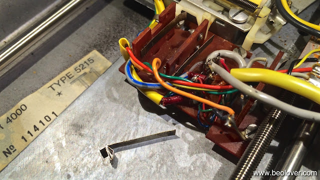
After I did PCB 7, I went on to fix the damaged output switch that is operated by the tonearm solenoid. Here is a picture of the tab as I found it. The output switch is the double switch in the center. It grounds the outputs when the arm is not in its down position.
It shows the usual signs of dilettante-intervention when a non-working switch is 'adjusted' in a vain attempt to make it work again. Once such a tab is bent, the only way to fix it properly is by taking it out and straighten it. Luckily it was the upper switch that needed this treatment, and so I did not have to take the board out. I was able to simply push the wires out of the way and desolder the tab:
I straightened it out and gave it a slight downward slant relative to the press-fit installation clamp at its end. Then I soldered it back in. This gave it a solid spring force towards the contact. It looks now like the tab of the other channel below:
After this I cleaned the other contacts (left is the carriage servo enable and on the right under the yellow cable the solenoid current limiter). Beautiful! This is beolove!


No comments:
Post a Comment
Comments and suggestions are welcome!