Featured Post

Beogram Commander Remote Control: Maybe This is the Final Version!..;-)

This is a follow up to my recent post about the redesigned Beogram Commander remote control board, which now works in both (DC-motor) Beogr...

Monday, September 26, 2016

Beogram 4002 (5501): Worn Keypad Restoration - My Process Finally Appears Reproducible...

The Beogram 4002 (5501) that I am restoring right now had the usual worn keypad. Here is an impression of how it looked before I restored it:
As usual the start button was worst...no surprise since it sees most of the action during normal play activities. This shows the keypad after my restoration procedure:

Nice! Looks almost like new!!...It took me a few months and many frustrating attempts to perfect my approach to rebuilding these keypads. But it seems my process finally yields a reproducible outcome. Another piece of the 4002 restoration puzzle in place! 

This keypad had one more issue: One of the RPM panel clamps was broken out preventing the RPM panel from staying down:
This shows the broken part in comparison with a good one that I had 'in stock':
I replaced it and now the keypad looks perfect. But I guess it is time to develop a 3D printed replica...Beolove never ends...;-)


Wednesday, September 21, 2016

Beogram 4002 (5501): Replacement of End Groove Detection Light Bulb with an LED

After restoring the RPM trimmer panel of the Beogram 4002 (5501) that I am rebuilding right now, it was time to look into the not working end groove detection mechanism. This mechanism is an exciting part of this design. It uses a light bulb and a photoresistor in conjunction with an encoder wheel doubling as pulley to detect the moment when the carriage starts moving faster after the last track of a record is over. This allows cutting short the time it takes until the arm returns to the home position on records that have a wide end groove section (such as many 12" singles or some short playtime LPs).

This shows the setup:
The bulb illuminates small holes that are in the pulley that is driven by the carriage motor. The light sensor is located on the other side of the spindle bearing. Unfortunately, the light bulb fixture of this Beogram had a broken off tab requiring some tape to hold it in place. Here is a picture of the bulb assembly pulled from the bearing unit:
The tab goes into the groove on top of the pulley bearing assembly. The back part of the tab is missing. You can also see very nicely the crack in the pulley. Nick is already working on a redesign of his standard aluminum pulley for the 4002 to add the small holes necessary for the end groove detection mechanism to work. Thanks Nick!

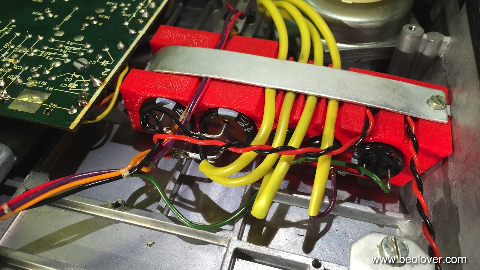
Naturally, this was not a Beolover acceptable state of affairs and so I designed a replacement part upgrading the system with an LED.

Here are a few impressions. This is the finalized component holding an amber high intensity LED (Newark 78R6602) and a 2k resistor (Newark 26R3983) reducing the current to below spec level of the LED. The resistor sits in a small holder on the left side to keep things neat and tidy:
This shows it illuminated at 23V:
And installed:
It press-fits right on top of the pulley bearing assembly
This shows it in action after the end groove circuit is activated via a carriage position switch:
I tested it and it seems to work great.

Here is an explanation how the end groove detection system works:
This shows the relevant section of the circuit diagram:
0IL1 is the LED. The switch 8009021 is the second carriage position switch on the B-rail:

Once 0IL1 comes on, the holes on the pulley begin to illuminate OR2. This causes voltage fluctuations across 1C35 which briefly turn off TR21. This applies a brief voltage pulse to C33 via D31 and R90. Hence, every time a hole of the pulley comes in between 0IL1 and OR2 a small amount of charge is put into C33. Therefore, over time the voltage on C33 increases proportionally to that charge. Once the voltage is high enough, TR20 turns on. TR20 is connected in parallel to the end switch ("ES", A), i.e. to the control system a TR20 in "ON" condition looks like ES was triggered and the arm lifts and the carriage returns home.

You may wonder, "what happens when the lamp turns on, but the needle is still on the last track of the record, and a pulley hole comes by and C33 charges up?" This is why D30 and R91 were added to the circuit as a (competing) path to discharge C33. R91 essentially determines the time it takes to discharge C33, and it was adjusted to discharge it fast enough to compensate for the charge build-up when the pulley only moves slowly when a track is played. In the end groove, however, the carriage moves much faster, and so the pulley holes come by more often, which overwhelms R91, and so the voltage can build up on C33, finally triggering the ES process.

If TR20 is not triggered due to a malfunction of the end groove detection system (dead bulb, for example), the arm will go all the way to the end of the end grove and then ES will be triggered by the carriage and save the day. All the end groove detection system does is to spare the user the wait until the arm goes all the way to the end (and to listen to the static from the groove). A typical B&O approach. Why not make it more perfect if you can?? This is Beolove!


Monday, September 19, 2016

Beogram 4002 (5501): Restoration of RPM Trimmer Panel

After rebuilding the PCBs of the Beogram 4002 (5501) that I am currently restoring, I turned my attention to the RPM trimmer panel. This panel had been replaced previously with the aim to repair a burned out trimmer scale illumination bulb. As a first step I re-worked the solder connections in the wires where the original panel had been cut off. This shows the situation when I received the deck:
I re-soldered all connections and installed proper diameter shrink tubing to protect the solder joints:
Then I replaced the bulbs with my LED replacement boards:
These are specially designed for the 550x Types since the bulbs partake in the RPM switching process, i.e. the LED circuits need to present a similar resistance/current draw as the original bulbs.
Like all my parts, these boards are available to other enthusiasts. Just send me an email, or use the contact form to the right. This video shows how to install the LED boards.

This shows the original situation (I already had removed one bulb when I remembered that I needed to take a picture...):
Then I installed the LED boards:
then I briefly confirmed that the LED replacements worked properly, and then I removed the white plastic fixture from the aluminum panel, since my customer wanted to use a different better-conditon panel instead of the one that was installed. This required to cut off the retaining rings on the aluminum posts after which I was able to remove the assembly:
What I found were already wavy white background strips that serve the back illumination of the ed RPM indicator hands. Wavy backgrounds cause inhomogeneous back illumination, i.e. they are better replaced if long term stability is desired. I usually replace them with white electrical tape:
After that I put the assembly on the new aluminum panel attaching it with M3 circlips and nylon washers. This shows the final outcome with the bulb covers installed over the LED panels:
And here an impression of the front side with 33 RPM selected:
Pretty! And it looks warmly incandescent (a result of using red and green LEDs to mimic the emission spectrum of incandescent light bulbs). All good again in the RPM panel department!


Saturday, September 17, 2016

Beogram 4002 (5501): Replacing all Electrolytic Capacitors

After fixing the strange control system issue it was time to plow ahead with the general restoration tasks, and so I replaced all electrolytic capacitors. This is always a good idea, since these units suffer from dried out capacitors, and Ta types can actually go up in flames when they expire. So replacing them with modern Aluminum 105C types is a good idea.

This shows the main PCB in its original condition:
And after replacing the capacitors:
After this I went under the keypad and extracted the output board. This shows its original condition:
And after replacing the output relay time delay capacitor and the old Siemens relay with a modern encapsulated unit:
Like all my parts the relay is available to other enthusiasts, just send me a message using the contact form on the left.
I also installed a grounding switch, which allows connecting signal and system grounds in case there is a hum in the output chain. This shows the switch from below:


Thursday, September 15, 2016

Beogram 4002 (5501): Repair of a Strange Fault Caused by a Shorted Diode D6

After replacing the reservoir capacitors in the Beogram 4002 (5501) that I am restoring right now, a strange control system malfunction remained. Here is a description:

After pressing START, the carriage would start moving but then after about 20 mm it would stop and the lights would go out. Then after a few seconds, the lights would come back on and the motor would run on 45 RPM. Once on 45 RPM, I was able to drive the carriage with the >> << buttons, but arm lowering would not work anymore. Switching back to 33 RPM killed everything again, but lowering would briefly function before the lights went out. Pretty strange all this!

Luckily the root cause turned out to be an easy fix. Here is the relevant part from my annotated circuit diagram:


After a bit of head scratching and doing some measurements, it occurred to me that a short circuited D6 would kill the 22V rail if TR2 is on, as it is the case when 33 RPM is selected. This was quickly confirmed by a 0V diode tester reading across D6 in both polarities. After replacing D6 with a new 1N4148 signal diode everything was working again properly.
This is how this fault 'worked': When TR2 is on then its collector is on GND level. If D6 is making a short, GND is applied to R2/D1 (dashed red lines). This kills the voltage on the base of TR1 which then kills the voltage on the base of 0TR1. This turns the 22V rail off and the lights go off. The time delay that was inherent in this process is enabled by C1, which preserves the base voltage on 0TR1 for a couple seconds until the capacitor is empty. At this point TR2 turns off. This allows the voltage to recover since now the anode of D6 is no longer grounded. So it does not matter if the diode is shorting. The voltage rail recovers, and that turns TR3 on via L1 and R8, and the deck is now operating on 45 RPM. Ahhh, the mysteries of analog control systems! This is Beolove!


Wednesday, September 14, 2016

Beogram 4002 (5501): Replacement of Reservoir and Motor Capacitors

The Beogram 4002 (5501) that I am restoring right now showed some erratic behaviors that indicated potential power supply trouble. When it comes to power everything starts at the reservoir capacitors and so I decided to put that on a solid footing. Many Beograms of that vintage suffer from dried out electrolytic capacitors, and replacing these big cans is always a good starting point for a restoration of the control system.
A look at the capacitors 'bank' of this early series 5501 immediately indicated that I needed to redesign my original 3D printed 550x capacitors fixture a bit to accommodate the thick yellow insulation tubes:
Here is the result:
I added the four deep 'half pipes' on the top part as seen here to make room for the insulation:
This allowed a neat installation:

Beautiful! Isn't it??
After I was done I checked the original 4000uF cans. Both were similarly out of spec:
While 2800uF for a 4000uF unit is clearly not acceptable indicating that the capacitors were on their way out, the new capacitors did not cure the erratic behavioral issues of the deck. So there must be something else amiss...on we go!...exciting! I always enjoy it if there is a previously unexperienced issue that one can try figuring out! This is Beolove!...;-)


CleanerVinyl Pro Released: Clean Up to 12 Vinyl Records in One Go!

A few of my CleanerVinyl customers inquired about a higher throughput version of my original CleanerVinyl design. The original design is very easy to use, but only allows the cleaning of one record at a time (that is why I rebranded it as CleanerVinyl One...;-). Inspired by these comments, I set out to do a redesign, which came together in the last few weeks. The new pro version is a much more massive design. It is built from precision-machined stainless steel and aluminum parts and also uses brass bearings to support the weight of the record stack. It can take on up to 12 records at a time. Check out my redesigned CleanerVinyl website, and the CleanerVinyl Pro video below. Enjoy!

Monday, September 12, 2016

Beogram 4002 (5501): Gold Plating of the Carriage Position Switch Spring Terminals

I am enjoying myself exploring the design of the early issue Beogram 4002 (5501) turntable that I am restoring right now. It is fascinating to see how the design evolved from the original Beogram 4000 design. After I rebuilt the arm lowering mechanism, I decided to take on the carriage position switches that are an exciting design feature of this 4002. The design is similar to the 4000 carriage position switches, but a bit improved. One of the weaknesses of the 4000 design is that the 7" record set-down point switch is a break switch, which has a tendency to cause problems when the switches oxidize. The reason for this is that a break switch depends on the spring force of the contact terminal to make the contact initially. A bit of oxidation, and the switch is permanently open, which severely disrupts the entire control system (usually the arm sets down immediately after pressing ON).

This potential issue was alleviated with the design under investigation here. Now the 7" detection is done with a standard make switch.
However, since these switches are the most likely sources of headache in these units, it is genrally a good idea to gold plate all their spring terminals. This prevents oxidation and so strongly reduces the probability of control system issues down the road. In this 4002 the switch actuators were also stuck due to hardened lubricants. So I took everything apart and lubricated the actuators and gold plated the terminals. Here are a few impressions:

This shows the switches after taking of the plate with the springs that push down the switches:

Point in case: The rightmost switch is stuck in down position.

Since the 550x Types were built before board to board connectors became prevalent in consumer electronics, one can only try to flip the board up for access to the switches and the plastic tabs that hold the actuator assemblies to the PCB. For this to happen the aluminum profile to the left needs to be pushed out of the way, which can be done after removing the two screws that hold it in place.
This shows the board after removal of the profile.
After unsoldering the leads of the carriage motor and of the end groove detection sensor, I lifted the board up and removed the actuators
and then the contact terminals (it is an excellent idea to do it in this order since it is very easy to damage the transparent plastic parts with the desoldering gun when taking out the terminals):
After cleaning the terminals with a fiberglass pen, I coated them with gold:
Nice and shiny!!

Then it was time to reinstall everything. First, I soldered the tabs back in:
They need to be flat against the PCB. Then I lubricated the red actuators and pushed their tabs back through the PCB (it helps to put a small dab of grease on each of the tabs, that prevents the necessity of applying much force, which keeps the small tabs from breaking off). 

This shows everything back in place:
All switches are up and they now move smoothly. I tried to run the turntable after this, but it turned out that there are still some major operability issues. The carriage motor only runs for a brief while after startup and the tracking sensor LED flickers while it does that...this indicates some severe power supply issues...this will be the topic of the next entry!


Sunday, September 11, 2016

BeoloverRPM: Redesign of Enclosure

No design is ever final! And so I completely revised the enclosure and the base-attachments for my BeoloverRPM device that allows the precise measurement of the RPM of a Beogram. A very useful tool for adjusting the RPM when servicing the deck, or for occasionally checking the RPM as the main belt ages etc...

I sold a number of them since I made the first design available in 2015, but it turned out that the 3D printing of the enclosure had some reproducibility issues due to my use of dovetails to match the different attachable bases with the main unit. Dovetails are difficult to print with 3D printers due to the need for exact tolerances, and today's consumer 3D printers are just not there yet.

So after I ran out of the BeoloverRPM units I manufactured with the original design, I decided to completely redesign the enclosure with the limitations of 3D printing in mind to fill a recent order. Here are a few impressions:

This is what is in the box:

On the right is the BeoloverRPM device with its sensor sticking out to the right. It has a small display that shows the RPM and min/max values as they establish over time. It can also send a stream of data to a computer via the USB port allowing the generation of a RPM vs. time curve. This is very valuable if there are intermittent RPM issues, that are often difficult to discern or reproduce when just listening to records.
The parts on the left are the three different bases, that can be attached to the main unit. They allow clamping to different Beogram chassises (they come in different metal frame strengths) when the deck is in service position, or putting it on top of the enclosure next to the platter. The unit is powered via a USB cable connected to a computer. This cable is also used to extract the data stream from the unit for RPM logging if so desired.

This shows the frame clamp in action:
and this shows it on top of the enclosure using the flat base attachment:
The functionality of the redesigned BeoloverRPM stayed the same, i.e. the demonstration in my video still applies. Check it out here.


Friday, September 9, 2016

Beomaster 8000: Awesome Find on Ebay!

I often help customers to find a suitable Bang & Olufsen unit on ebay or craigslist, then restore it and then send it on to its new home. Almost like going back to the 70s with a time machine and buying it new at a B&O store...;-). Here the task was to find a Beomaster 8000 in nice cosmetic condition. I always recommend to start any restoration with a nice looking unit, since the value of the finished unit is largely determined by its looks...

Recently a very nice Beomaster came up on ebay including the Terminal remote and the original packaging. It was also sold by the initial owner - always a very good sign! I received the unit yesterday, and it was a happy moment. He had the original box double boxed by a mailing place, and so it arrived in a  huge box under a heap of styrofoam peanuts...not my favorite method - too messy when unboxing and more importantly, the inner box can shift around and individual sides of the inner box can end up dangerously close to the outer box, negating the purpose of the double box. In this case all went well, though.

Here are a few impressions:
As I said, a LOT of peanuts...;-). After I shoveled everything in several lawn bags, I extracted the original box:
then came the moment of truth!:
The original owner's manual! excellent! And then the Beomaster revealed itself:
In pristine condition as advertised! I love it when ebay sellers are honest! In this case it was a very pleasant experience from A to Z. Look at the veneer corners!:
Awesome! Almost like new! The best corners I have seen in some time! Lucky day!