Featured Post

Beolover SyncDrive: DC Platter Motor Replacement for Beogram 4002 and 4004 (Type 551x and 552x)

Late Beogram 4002 and the 4004 (Types 551x and 552x), which have DC platter motors instead of the earlier synchronous AC motors usually suff...

Wednesday, September 14, 2016

Beogram 4002 (5501): Replacement of Reservoir and Motor Capacitors

The Beogram 4002 (5501) that I am restoring right now showed some erratic behaviors that indicated potential power supply trouble. When it comes to power everything starts at the reservoir capacitors and so I decided to put that on a solid footing. Many Beograms of that vintage suffer from dried out electrolytic capacitors, and replacing these big cans is always a good starting point for a restoration of the control system.
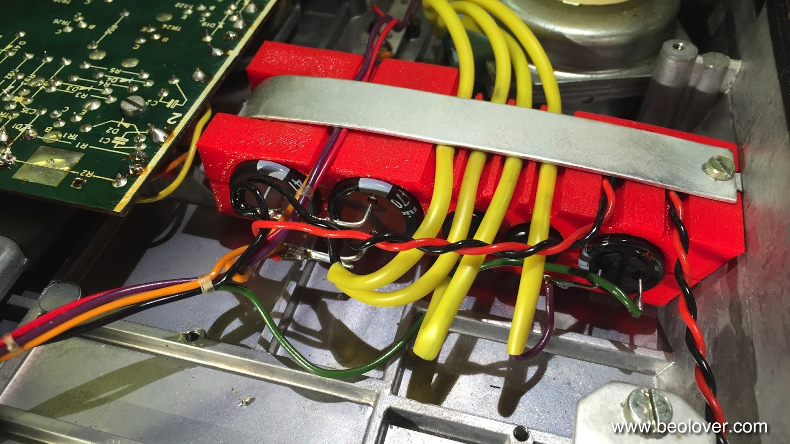
A look at the capacitors 'bank' of this early series 5501 immediately indicated that I needed to redesign my original 3D printed 550x capacitors fixture a bit to accommodate the thick yellow insulation tubes:
Here is the result:
I added the four deep 'half pipes' on the top part as seen here to make room for the insulation:
This allowed a neat installation:

Beautiful! Isn't it??
After I was done I checked the original 4000uF cans. Both were similarly out of spec:
While 2800uF for a 4000uF unit is clearly not acceptable indicating that the capacitors were on their way out, the new capacitors did not cure the erratic behavioral issues of the deck. So there must be something else amiss...on we go!...exciting! I always enjoy it if there is a previously unexperienced issue that one can try figuring out! This is Beolove!...;-)


CleanerVinyl Pro Released: Clean Up to 12 Vinyl Records in One Go!

A few of my CleanerVinyl customers inquired about a higher throughput version of my original CleanerVinyl design. The original design is very easy to use, but only allows the cleaning of one record at a time (that is why I rebranded it as CleanerVinyl One...;-). Inspired by these comments, I set out to do a redesign, which came together in the last few weeks. The new pro version is a much more massive design. It is built from precision-machined stainless steel and aluminum parts and also uses brass bearings to support the weight of the record stack. It can take on up to 12 records at a time. Check out my redesigned CleanerVinyl website, and the CleanerVinyl Pro video below. Enjoy!

Monday, September 12, 2016

Beogram 4002 (5501): Gold Plating of the Carriage Position Switch Spring Terminals

I am enjoying myself exploring the design of the early issue Beogram 4002 (5501) turntable that I am restoring right now. It is fascinating to see how the design evolved from the original Beogram 4000 design. After I rebuilt the arm lowering mechanism, I decided to take on the carriage position switches that are an exciting design feature of this 4002. The design is similar to the 4000 carriage position switches, but a bit improved. One of the weaknesses of the 4000 design is that the 7" record set-down point switch is a break switch, which has a tendency to cause problems when the switches oxidize. The reason for this is that a break switch depends on the spring force of the contact terminal to make the contact initially. A bit of oxidation, and the switch is permanently open, which severely disrupts the entire control system (usually the arm sets down immediately after pressing ON).

This potential issue was alleviated with the design under investigation here. Now the 7" detection is done with a standard make switch.
However, since these switches are the most likely sources of headache in these units, it is genrally a good idea to gold plate all their spring terminals. This prevents oxidation and so strongly reduces the probability of control system issues down the road. In this 4002 the switch actuators were also stuck due to hardened lubricants. So I took everything apart and lubricated the actuators and gold plated the terminals. Here are a few impressions:

This shows the switches after taking of the plate with the springs that push down the switches:

Point in case: The rightmost switch is stuck in down position.

Since the 550x Types were built before board to board connectors became prevalent in consumer electronics, one can only try to flip the board up for access to the switches and the plastic tabs that hold the actuator assemblies to the PCB. For this to happen the aluminum profile to the left needs to be pushed out of the way, which can be done after removing the two screws that hold it in place.
This shows the board after removal of the profile.
After unsoldering the leads of the carriage motor and of the end groove detection sensor, I lifted the board up and removed the actuators
and then the contact terminals (it is an excellent idea to do it in this order since it is very easy to damage the transparent plastic parts with the desoldering gun when taking out the terminals):
After cleaning the terminals with a fiberglass pen, I coated them with gold:
Nice and shiny!!

Then it was time to reinstall everything. First, I soldered the tabs back in:
They need to be flat against the PCB. Then I lubricated the red actuators and pushed their tabs back through the PCB (it helps to put a small dab of grease on each of the tabs, that prevents the necessity of applying much force, which keeps the small tabs from breaking off). 

This shows everything back in place:
All switches are up and they now move smoothly. I tried to run the turntable after this, but it turned out that there are still some major operability issues. The carriage motor only runs for a brief while after startup and the tracking sensor LED flickers while it does that...this indicates some severe power supply issues...this will be the topic of the next entry!


Sunday, September 11, 2016

BeoloverRPM: Redesign of Enclosure

No design is ever final! And so I completely revised the enclosure and the base-attachments for my BeoloverRPM device that allows the precise measurement of the RPM of a Beogram. A very useful tool for adjusting the RPM when servicing the deck, or for occasionally checking the RPM as the main belt ages etc...

I sold a number of them since I made the first design available in 2015, but it turned out that the 3D printing of the enclosure had some reproducibility issues due to my use of dovetails to match the different attachable bases with the main unit. Dovetails are difficult to print with 3D printers due to the need for exact tolerances, and today's consumer 3D printers are just not there yet.

So after I ran out of the BeoloverRPM units I manufactured with the original design, I decided to completely redesign the enclosure with the limitations of 3D printing in mind to fill a recent order. Here are a few impressions:

This is what is in the box:

On the right is the BeoloverRPM device with its sensor sticking out to the right. It has a small display that shows the RPM and min/max values as they establish over time. It can also send a stream of data to a computer via the USB port allowing the generation of a RPM vs. time curve. This is very valuable if there are intermittent RPM issues, that are often difficult to discern or reproduce when just listening to records.
The parts on the left are the three different bases, that can be attached to the main unit. They allow clamping to different Beogram chassises (they come in different metal frame strengths) when the deck is in service position, or putting it on top of the enclosure next to the platter. The unit is powered via a USB cable connected to a computer. This cable is also used to extract the data stream from the unit for RPM logging if so desired.

This shows the frame clamp in action:
and this shows it on top of the enclosure using the flat base attachment:
The functionality of the redesigned BeoloverRPM stayed the same, i.e. the demonstration in my video still applies. Check it out here.


Friday, September 9, 2016

Beomaster 8000: Awesome Find on Ebay!

I often help customers to find a suitable Bang & Olufsen unit on ebay or craigslist, then restore it and then send it on to its new home. Almost like going back to the 70s with a time machine and buying it new at a B&O store...;-). Here the task was to find a Beomaster 8000 in nice cosmetic condition. I always recommend to start any restoration with a nice looking unit, since the value of the finished unit is largely determined by its looks...

Recently a very nice Beomaster came up on ebay including the Terminal remote and the original packaging. It was also sold by the initial owner - always a very good sign! I received the unit yesterday, and it was a happy moment. He had the original box double boxed by a mailing place, and so it arrived in a  huge box under a heap of styrofoam peanuts...not my favorite method - too messy when unboxing and more importantly, the inner box can shift around and individual sides of the inner box can end up dangerously close to the outer box, negating the purpose of the double box. In this case all went well, though.

Here are a few impressions:
As I said, a LOT of peanuts...;-). After I shoveled everything in several lawn bags, I extracted the original box:
then came the moment of truth!:
The original owner's manual! excellent! And then the Beomaster revealed itself:
In pristine condition as advertised! I love it when ebay sellers are honest! In this case it was a very pleasant experience from A to Z. Look at the veneer corners!:
Awesome! Almost like new! The best corners I have seen in some time! Lucky day! 


Wednesday, September 7, 2016

Beogram 4002 (5501): Restoration of the Arm Lowering Mechanism and Installation of a New Tracking Sensor Light Source

I started the restoration of this (exciting) early 5501 type Beogram 4002 that came from the UK to my bench with the rebuilding of the arm lowering mechanism. The first step of this procedure is to remove the solenoid linkages and the damper for inspection/cleaning and re-lubrication. This shows the assembled mechanism:
This shows the disassembled and cleaned components:

The next step is to do the same for the damper-to-arm linkage. In order to get to its pivot point that needs new lubricants, one has to take out the sensor arm:
This shows the arm sideways on a piece of cloth. Removal of the retaining washer and the small spring that is underneath (careful here, if you do that at home...this spring is important but quickly lost) allows the removal of the linkage:

After the linkage is reinstalled, the arm ends to be re-implanted. At this point it is important to get the lateral parallelism properly adjusted:
The arms need to be parallel and perpendicular to the rods on which the carriage travels.
After that the vertical parallelism can be adjusted with a set screw in the back of the arm assembly:
The arms need to be at the same height (I apologize for the slightly unfocused picture taken in the 'heat of battle'...;-).

The final step is to install a new tracking sensor light source. The old lightbulbs are pretty fragile at this point in time, and so the installation of an LED based replacement is recommended to ensure day-to-day use reliability.
This shows the original light source with its black light shield:
I used a SMD LED based replacement part that I designed a while ago. It represents an improvement, not only in longevity, but also in function since it has a Beogram 4000 inspired trimmer that allows adjusting the light intensity. This is very convenient when it comes to the fine tuning of the tracking sensor feedback. I will do this procedure at a later point in time, since a few other things need to be sorted out with this lovely Beogram before I can adjust the tracking mechanism. Here is an impression of the new part installed:
The next steps will be fixing the cracked pulley and the broken end groove detection sensor, and to get the carriage position switches back into spec. 


Monday, September 5, 2016

Beogram 4002 (5501): A New Arrival from the UK

Beolover's joyful summer travel has come to an end! Time to get back to the bench!
Last week a lovely Beogram 4002 (5501) arrived for some TLC from the UK. The exciting part here is that this particular unit is an early style 5501 model that has a few interesting design features that can be regarded as stepping stones between the original Beogram 4000 design and the later 4002 types.
The unit came well packed and shipping was arranged by parcelhero.com. I really like parcelhero. They offer fully tracked express service between the UK and the US. It usually only takes only an impressive 3-4 days door-to-door, and the price is about the same like standard international snail mail. Just outstanding. I really wish we had something like this in the US...
Anyway, after digging out the original B&O box from about 4 cubic yards of bubble wrap (better too much than too little!..;-), I extracted the 4002 from its styrofoam protectors and set it up on my bench:
The overall condition of the unit is pretty good, albeit the keypad has worn areas
and there is a bit of veneer missing from the plinth:
Under the hood is seems pretty original, at least there are no obvious signs of human creativity,
Except that there was a unique grounding wire installation, which used one of the support spring screws as terminal:
The brown cable let do a switch on the outside:
Obviously someone experienced intermittent grounding issues, possibly due to a RCA adapter missing a broken out grounding lead. I removed this construction.
While we are looking at cables, here is a picture of the interesting UK plug that was installed:
Looks a bit like a tea kettle, doesn't it??..;-)

I temporarily exchanged it with a US plug allowing me to operate the unit from a standard US outlet (I also put in temporary 500mA fuses replacing the original 250mA types that are used in the 220-240 environment to account for the double current that will flow while it is operated at 110V).

The exciting parts are the design specifics of this model. This shows the (broken, hence the tape) end groove detection set-up that is mounted on the spindle pulley:
The light bulb illuminates the spindle pulley, which has four holes. Through these the light illuminates a photosensor. This allows the detection of the spindle speed, which can be used to detect that the needle is in the end groove, where the carriage moves faster than usual. This mechanism replaces the servo-voltage based set-up that is used in the Beogram 4000. One could think of this mechanism as an analog rotary encoder...just awesome!

The metal plate in front of the encoder holds the springs that actuate the switches that are used for position detection, similar to the setup found in the Beogram 4000. This was later replaced by an optoelectronic mechanism using a plexiglass bar with blacked out regions to block light from a bulb or IR LED. Here is another view of this setup:
Upon further inspection I found that one of the springs that hold up the bolts that connect the hood hinge to the chassis is missing:
I usually replace these with springs from ball point pens...;-)

After this first look I tried to start the unit up. There were life signs, but the carriage was a bit sluggish...so the mechanical restoration of the carriage drive system and arm lowering mechanisms will be the first items to look at when I start this restoration.