Featured Post

Beolover SyncDrive: DC Platter Motor Replacement for Beogram 4002 and 4004 (Type 551x and 552x)

Late Beogram 4002 and the 4004 (Types 551x and 552x), which have DC platter motors instead of the earlier synchronous AC motors usually suff...

Friday, December 18, 2015

Beogram 4002 (5521): Adjusting Platter and Chassis

The looks of a Beogram 400x strongly depend on the platter being properly aligned with the aluminum panels surrounding it. When correctly done the platter aluminum surface is flush with the surrounding panels, i.e. the black 'ribs' on the platter protrude above a flat aluminum surface. This adjustment is pretty tricky since several parameters must be brought in alignment. Over time I found that this adjustment is often complicated by a sensor arm that is not completely parallel to the floating chassis plane. The adjustment procedures outlined in the service manual and featured in my videos is based on the assumption that the sensor arm is parallel, i.e. if it is not the process gets 'distorted' and one ends up with one or more parameters out of spec once the platter is flush with the aluminum surfaces (most often the resulting problem is that the chassis is tilted after the adjustment in such cases and therefore chafes with the transport lock bushings).

So my most recent approach is to first get the sensor arm as parallel as possible to the floating chassis that holds the platter. The arm is on the carriage which travels on two precision rods that are held in fixtures where the rod height can be adjusted with set-screws from below. This picture shows one of these fixtures:


Unfortunately, the adjustment of these screws would require to remove the floating chassis, which is a bit painful.

This led me to a different approach: First I disconnected the floating chassis from the leaf springs that hold it up that it sat flat on the 'floor' of the enclosure. Then I put in the aluminum panels and measured the parallelism of the sensor arm relative to the panels at the lateral locations of the two rods. In this particular case I identified a 1.5 mm difference between the back and the front rod locations. Then I designed 3D printed spacers to lift the front rod up by 1.5 mm:


I did the same for the other end of the rod. Now the arm was parallel:

The next step was to get the platter parallel to the sensor arm in a 23 mm distance between top of the arm and the platter aluminum surface. Essentially I did the procedure shown in my video. Basically, what you should find is that the platter should be pretty close to parallel to the arm with the bearing fully screwed down if the arm is really parallel to the chassis. After this it was time to float the chassis again and adjust the springs until the platter was flush with the aluminum plates:


Ahhh...so beautiful! This is Beolove!


Thursday, December 17, 2015

BeoloverRPM: Beogram RPM Calibration Device

Sadly, the Beogram 4002 that I restored a little while ago did not pass muster. It had initially come  to me with an indication of sudden and gradual RPM fluctuations and I thought I had fixed the issue by replacing the RPM relay and the trimmers as well as the DC motor, which showed a strange feedback signal whenever the fluctuations occurred. But not so. While the phenomena were somewhat alleviated, some spontaneous variation still occurs occasionally. Per my customers description it happens maybe once per LP, i.e. it needs to be treated as an intermittent issue. Which are notoriously difficult to fix. 
I decided I needed to be able to measure and quantify the issue before I would be able to attempt another stab at fixing it. The Beolover never gives up, but this one is a tricky one. The last few days I worked on designing the "BeoloverRPM" device, which now allows me to quantify and monitor the RPM of a Beogram with fairly high precision (I think it maybe about 0.03%) over time. I also implemented an automatic fluctuation detection mechanism based on monitoring the standard deviation of the measurement. 

I designed a sensor head, which uses the black ribs found in the Beogram 400x and 800x models to detect the RPM of the platter. Here are a few impressions. The front is curved to fit the platter circumference, and the reflective optosensor unit extends via a fork over the platter

I implanted two M8 bolts into the back of the unit to give it some more weight so it would sit securely next to the platter:

Here is is shown in action measuring the platter of the Beogram 4000 that I just finished up:

It appears to be floating due to rubber feet inserted into the bottom of the body (I was inspired here by the Beogram 8000's rubber bumpers that dampen the impact of its hood when it closes)
The most crucial design parameter was the distance between sensor and measured features. Its optics are fixed, and I determined the best measurement resolution results at a distance of 9 mm. I printed several versions of the housing until I got that distance about right.

Once I had the sensor and verified that I could use it for RPM measurements I sat down and programmed an Atmega328p (aka Arduino) to measure the RPM and do some statistical evaluations. At this point the firmware is able to log the RPM and the standard deviation in timed intervals (10s in the example below). It also detects sudden deviations through monitoring the difference between the running mean of the standard deviation and the current standard deviation. This difference is quite sensitive and a proper threshold allows to hone in on a certain level of fluctuation.

Here is an impression of the printout that is generated:

The ***-marked % deviations were the result of slightly touching the platter with my finger a couple of times. It is interesting to note that the RPM shows as ~33.71 even though I calibrated the RPM of the Beogram 4000 using the AC motor frequency as specified in the Service Manual. It is obvious that this calibration is about 1% off. Naturally I wondered if a measurement error would be responsible for the discrepancy, but a test of the BeoloverRPM device on my Beogram 8000 revealed a proper measurement of 33.32 RPM, which is very close and possibly even at least partly a result of the Beogram 8000 being slightly off (the Service Manual specifies a 0.02% RPM accuracy).
As a next step I will implement an external trigger function for my oscilloscope that I can measure the vitals of a turntable at the moment a fluctuation occurs. Hopefully, this will allow me to figure out what the issue is with the fluctuating 4002! This is Beolove!


Sunday, December 13, 2015

Beogram 4000: Polishing the Hood and a Strange Hinge Pin

I am giving the Beogram 4000 that I restored recently the final touches. The last item to check off on the list is always polishing the hood. Like most Beograms that I saw so far this one also had a badly scratched up hood from carelessly stapling things on top of it while it sat in 'storage'. This unit had a couple more items that needed to be taken car of: One of the hinge pins was not original. At some point the short press-fit pin must have 'vanished' (one really wonders why someone would take it out...but such is the human creativity...;-), and a replacement pin was installed. The 4 mm replacement pin fit well into the hinge parts, but was too long and so it stuck out a bit:

Here a picture from the bottom of the hinge assembly:
I took the pin out and cut it by 4 mm with a jig saw and a metal blade. That allowed the pin to be inserted a bit deeper and it looks original now:
On the other side of the hood the aluminum trim had come off from the plexiglass:

I fixed that by applying a strip of double sided tape and pressing the strip back to the hood body. I recommend to not use epoxy or similar glue for this since the aluminum strip covers the screws that hold the hood to the hinge, and if the hood ever needs to be take off the trim needs to be pried off.

Anyway, after these tasks I set out to polish the hood. this one was special since it also had some issues on the inside, which is much more difficult to fix since it is hard to polish the inside. Luckily the damage was fairly small and most of it appears to have been tape residue:

I was able to remove it with a bit of detergent and a Mr. Clean Magic Eraser Pad. After that it needed a bit of buffing with polishing fluid, and that seems to have done the trick. There are a few more small very localized dings on the inside, but I chose to let them be since it is almost impossible to to a full sanding/polishing job on the inside since one cannot get to the corners.

Then I focused on the main job, the outside of the hood. Here are a couple impressions of the degree of scratching:


Nothing too special, but the depth of the damages required to start out with 200 grit sand paper to level the surface with the deepest damages:

This was followed with 320 grit:
and 400 grit, the first wet-sanding step:

It starts getting clearer already, but a full treatment with Micro-Mesh is required to get back to a fully translucent state:


And finally after buffing it with polishing fluid:

all good in the hood department now! A few more days of testing and this Beogram 4000 is ready for its journey back to Italy!


Thursday, December 10, 2015

Beogram 4002 (5521): Replacing the Electrolytic Capacitors, New Relays and New RPM Trimmers

It was time to replace the electrolytic capacitors of the Beogram 4002 that is currently on my bench. These units have many tantalum capacitors, and it is a good idea to replace them at this age. They can die a fiery death due to the highly oxidizable nature of the Ta electrodes in them. Here is a picture of the original board. All the blue and red 'dots' are Ta capacitors:


Another standard item of my restorations is to replace the trimmers and the relay in the DC motor RPM control network. Oxidized trimmers can cause drift of the platter speed depending on the temperature of the deck (and the moon phase...;-), while the relay is not encapsulated and hence prone to oxidized contact issues after almost 40 years of service.

I recently developed a replacement relay assembly for the Beogram 4000 and early 4002 models based on a modern encapsulated SMD signal relay. However, this Beogram is a later model, which was already fitted with a more modern relay made by National. This relay is still available as new original stock (NOS) via vendors on AliExpress and similar Asian outlets. However, modern relays are much superior in their design due to modern encapsulation technology and the promise to last for many decades. It is good to keep in mind here that NOS parts are still 30-40 years old and old technology, they just were not used. But oxygen hat its go on them, and so we can expect that the contact tabs are almost as oxidized as in the relay installed in this Beogram 4002!

Hence I modified my design to fit into the later models, too. Here is a picture of the revision of the drop-in replacement relay assembly:
This picture shows the 25 turn 5k trimmers prepared for installation:
This is a picture of the main PCB after replacing everything:

A detail of the relay and RPM trimmers together with the original relay:

This shows the trimmers from the top side of the PCB:
It is important that they are accessible from the top, so one can trim the RPM while the deck is running without having to take out the main PCB.

When replacing the capacitors, of course the main reservoir capacitor of the power supply also needs to be replaced. This shows the original can:

And here the replacement:

I designed a 3D printed adapter enabling me to clamp a modern 4700uF capacitor in the space of the original unit.

After the main PCB I did PCB #8 that sits underneath the keyboard, and which contains the output relay. Here is a shot of the original unit:
I usually install a new relay, replace the time constant capacitor for the relay, and also install a grounding switch that allows to tie system and signal grounds together if necessary to squash humming issues. Here is a picture of everything installed:
After these replacements I put everything back together and then I tested the unit...all went well. This concludes the electronic rebuild. On to the adjustments and alignment of the platter, chassis and the arms!


Monday, December 7, 2015

Beogram 4000: Adjusting the Tracking Force and Replacing the Strange Original Front Center Cabinet Guiding Washer

The Beogram 4000 that I just finished up is now running smoothly. I am playing 'Song for My Father' by Horace Silver (unfortunately a reissue, since the original first pressings are unaffordable these days...sigh!!), which is one of my favorite jazz tunes while writing this post.
Before I got here, however, I still had to do a bit of work on this Beogram: Adjusting the tone arm weight and limits. I also replace the strange standard guiding washer that is typically found installed in the front center guiding slot to ensure a straight movement of the plinth when it is pushed back to secure the aluminum panels. Here is a picture of the original washer including the shoulder bolt:


This awkward setup just does not work well, and consequently later Beogram 400x have a much better design based on an eccentric washer shape. I recently designed 3D printed replicas of this design since they often crack in 4002 and 4004 models that are outfitted with plastic versions of it. See this video for their installation. The parts are available via my Shapeways store (five washers are needed to replace all of them).

Here is a picture of the new washer installed together with a new M3 bolt (note the much lower profile of the assembly, which is beneficial when installing the aluminum panels as chafing is avoided):


After this small detail, I did the arm adjustment. Most important are the zero weight and tracking force calibration and the proper adjustment of the arm lowering limit, which can be the final stop gap that keeps the platter from ripping the needle out of the MMC cartridge in case of a failing photosensor or misadjusted sensor bulb. Earlier I posted videos about these two procedures (tracking force calibration, arm lowering limit). Equally important is the improvement of the weight adjustment screw assembly, which I usually upgrade with a M3 nut and washer. This allows to permanently fix the adjustment in place, which is critical for a successful out-of-the-box setup when I send the turntable back to Italy. The original setup with the locking washer is too flimsy, which can result in a change of the calibration during shipment. Here is a picture of the installed nut:

And here the needle on the tracking force gauge at 1g after adjusting everything:

Ah...Horace Silver via a perfectly adjusted 4000 and my Beomaster 6000 4-Channel - perfect pairings!...I am in Beoheaven..;-)


Beogram 4002 (5521): Replacing the Deteriorated Transport Lock Bushings

The Beogram 4002 that I am restoring right now came with decayed transport lock bushings. A tell tale sign of this issue is the random distribution of small orangish plastic fragments throughout the enclosure after shipping.

A while ago I designed 3D printed replacement bushings that can conveniently be inserted with the sub-chassis in place. This is achieved through the use of two halves that can be installed from the top and from below. Here is a picture of the parts:

If you are interested they are available via my Shapeways store. Each bushing requires two of the parts. A video about the installation process is posted here. It is important to not confuse the upper and lower brackets of the lock assembly since they have opposite threads, i.e. it is best to mark the top one before taking it out to get at the bushings.

Here are a few impressions of restoring the bushings in this particular unit. This shows the cracked original bushing of the lock at the front:

This shows the lower half of the replacement bushing inserted into the cleaned up opening:

And here a picture after inserting the top half.

I did that for the other two, too. A bit of cleanup of the fragments with a computer vacuum, and all was good again!


Saturday, December 5, 2015

Beogram 4002 (5521): Replacing the RPM Scale Illumination Bulbs with SMD LEDs

After replacing the broken light source of the tracking sensor, The next step of my current Beogram 4002 (5521) restoration was to replace the incandescent light bulbs in the RPM trimmer panel. The 33 RPM bulb was burned out, so we decided to replace both bulbs with my drop-in SMD LED assemblies. I am using red-green LEDs to ensure that there is a red light component to ensure proper illumination of the red RPM indicators. While amber LEDs can result in an incandescent-like look, they are not able to properly illuminate red surfaces due to their narrow wavelength distribution. Here is a picture of the small circuit boards that carry the LEDs as well as two current limiting resistors, one for the red and one for the green LEDs. This allows to tune the relative intensities to achieve an authentic looking illumination:

I recently made a video that shows how to exchange the bulbs with these boards. They are available to other enthusiasts. Just send me an email. 

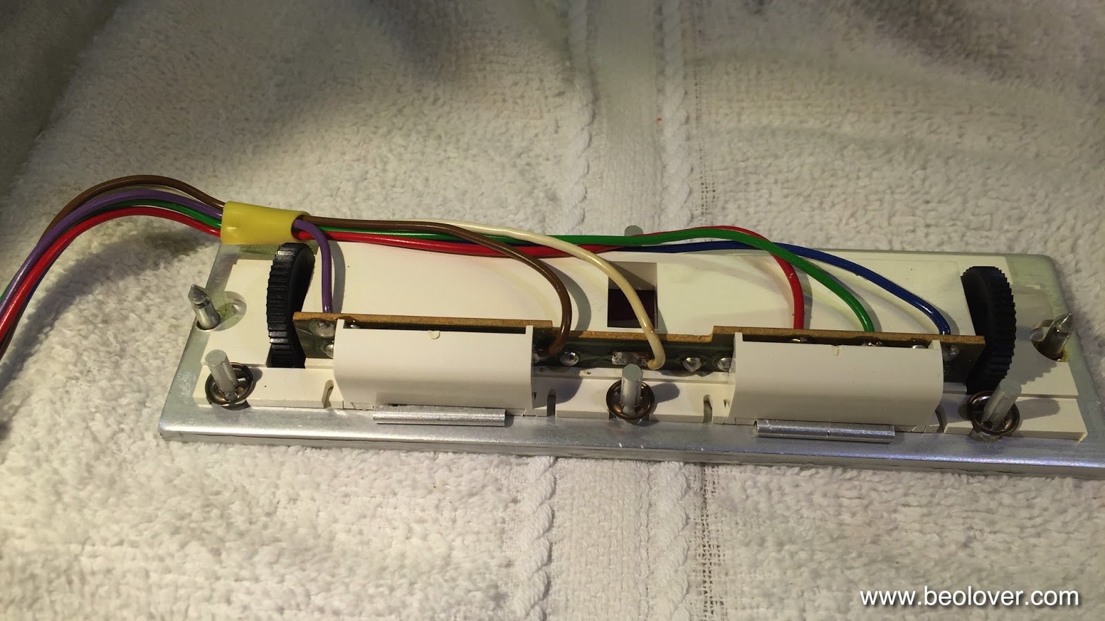
Here are a few impressions of the installation in this particular Beogram. This shows the trimmer panel after removal:

The bulbs can be accessed after removing the two covers:

After unsoldering the leads the bulb assemblies can be slid out:

Now the PCBs can be installed. It is important that they sit flush with the aluminum surface:

And then the covers can be replaced:

And that is it!