Featured Post

Beogram Commander Remote Control: Maybe This is the Final Version!..;-)

This is a follow up to my recent post about the redesigned Beogram Commander remote control board, which now works in both (DC-motor) Beogr...

Thursday, December 31, 2015

Beogram 4002 (5513): Repair of a Broken SO ('Shut Off') Switch

This is a follow up to my last post about a SO ("Shut Off") switch that had lost its plastic actuator and hence caused trouble during shutdown of the deck. I set out to develop a 3D printed part to replace the missing plastic part. This shows the SO (left) and the ES ("End Switch", right) in comparison. The ES still has its plastic appendage, while the SO is missing it.

I took measurements and then went through a few 3D printing iterations to get a part that would come out right. Due to the small size this was pushing the limits of the 3D printer, so the outcome was significantly difficult from the 3D CAD design, and experimentation finally yielded a useful shape:

I glued it on with epoxy:
And now this Beogram can shut down again in an orderly manner:

On to the sub-chassis and platter adjustment.


Tuesday, December 29, 2015

Beogram 4000: A New Pulley, Hood Bumpers and Shipping Back to Italy

The Beolover always strives to improve his craft and get things as perfect as possible. So I realized that I was not fully done yet with the restoration of the Beogram 4000 from Italy. My recent efforts to restore a Beogram 8000 from Japan introduced me to the concept of rubber hood bumpers that soften the impact if the hood is closed. It makes quite a big difference in terms of how it feels to close the hood. The sound when the hood seats on the enclosure is just so much more solid when the bumpers are present. Unfortunately they all seem gone at this point in time, and that is the reason that it took me some time to realize that all the classic B&O decks actually have(had) them! All that is usually left are some small holes filled with black degraded rubber remnant. This shows how it looked on the hood of the Beogram 4000:
It is easy to get the black stuff out with a 2 mm drill bit operated by hand (do NOT put it on a Dremel or similar...it is easy to damage the plexiglass):
Like with the Beogram 8000, rubber O-ring segments work well to restore the bumpers. In the case of this 4000, however, I needed to use 2mm diameter metric ones since the 0.1" type I used on the Beogram was too thick to squeeze into the holes. I glued the segments in with a bit of contact glue on the tip of the segment. Then I used my 3D printed cutoff template that I developed for the Beogram 8000 and razorblades the excess length off:
A perfect-length bumper resulted:
It has the right length to right the hood into a horizontal alignment with the plinth. The way the hinges are designed at the back of the hood, a ~1mm gap should be around the entire perimeter between hood and plinth if the hood is to be perfectly horizontal. These bumpers guarantee that. Beautiful!

Beyond this issue I also was a bit annoyed that the carriage ran a bit noisily when returning to the home position after a record was played to the end or OFF pressed. This was the result of a somewhat wobbly pulley, a result of a crack in its set screw assembly:

I exchanged it with a custom manufactured Aluminum pulley provided by Nick (via www.beoworld.org):
This fixed the issue and also looks beautiful. I think I will make this a standard part of my restorations since most pulleys are (or will be soon) cracked and/or run wobbly. This pulley quieted the mechanism down quite a bit and made it much more pleasant to use this Beogram 4000!

After these two tasks it was finally time to send it off. My customer requested state-of-the-art Beolover double boxing, and so I used this occasion to make a short video about the proccess:


May the Force (and gentle FedEx men&women) be with you on your way to Italy!


Beogram 4002 (5513): Rebuilding the Arm Lowering Mechanism, Mechanical Adjustments and a Broken SO Switch

Today I rebuilt the arm lowering mechanism of the Beogram 4002 (5513) that recently arrived on my bench. It turned out that all linkages were stuck and that the damper was completely dry. The first step was to re-lubricate the damper to arm linkage and adjust the lateral arm parallelism. I took out the sensor arm fixture to get to the pin around which the linkage rotates:

Then I took the mechanism apart and cleaned everything of the hardened lubricants and re-lubricated with a small amount of silicone grease:

Then I put everything back together and made sure the arms are parallel. Then it was time to extract the damper and the solenoid linkages:

Here is a picture of the damper taken apart:
I lubricated it with a bit of synthetic motor oil and cleaned the old lubricants fro the linkage pivot points and re-lubricated those with silicone grease. Then I put everything back together and gave it a spin. While the arm was now lowering properly, the tracking mechanism was completely out of adjustment due to the arm alignment. So I had to adjust the tracking feedback. Hence it was time to crank out my least favorite record and stick on my dented MMC20EN cartridge to adjust the mechanism:

I made a detailed video about this process, which explains how to do it properly.

Then it was time to adjust the arm lowering limits to help prevent a cantilever extraction in case the sensor in the sensor arm dies. There is another video that shows how to do this. This was the result of my efforts:


The stylus is supposed to just clear the lower parts of the platter ribs when all the way lowered. The final task was to adjust the tracking force. Yet another video shows how to do that.

Then I played a record, which went well, but I had to realize that the 'Switch Off' (SO) switch that turns the deck off when the carriage is in its home position is broken. It is interesting to note how this manifested itself: When the arm returned to its home position on the right, the deck shut down, but the solenoid briefly came on and jerked with a loud 'clonk'. The reason for this is a missing plastic part that is needed to fully engage the switch, i.e. make the ground connection at the right point during the home movement of the carriage. Here is a picture of a good SO switch in a different Beogram 4002:

And here the broken one:

Note the missing small black plastic part right above the carriage pulley. If it is not there the switch terminals are not moved far enough by the aluminum tab on the position ruler preventing it from switching over to the GND pole. However, without the plastic part the switch the switch also forms a ground connection via the aluminum tab on the position indicator slide that is activating it when the carriage has arrived in the home position. This turns the deck off like a working SO switch, but a bit too early and perhaps with a bounce since the spring force between the tab and the switch terminal is weak. Hence the solenoid jerk.


Sunday, December 27, 2015

Beogram 4002 RIAA Preamplifier: First Prototype Installed

I was asked to design an internal RIAA preamplifier for the Beogram 4002 (5521) that I recently restored. An internal preamplifier is an excellent idea since many modern receivers do not feature a dedicated phono input anymore. Also, the RIAA preamps of many classic B&O receivers are pre-opamp designs and therefore have a higher noise floor than what can be achieved with dedicated modern low-noise audio opamps.

After doing a bit of research about modern RIAA preamp designs I settled for the LM833 operational amplifier, which is an optimized low-noise design for audio applications. I based my design on a precision RIAA preamp circuit described in the Texas Instruments application note AN-346. There is really no need to re-invent the wheel when it comes to RIAA preamps, this has been figured out long ago.

I added a rail spitter to create a virtual ground for the opamps since the Beogram only has a positive power rail. It turned out that I needed to run the preamp from the 31V rail, since the regulated 21V rail introduced a significant amount of motor EMF into the amplifier circuit resulting in a loud hum clearly depending on the motor RPM. Using a 24V regulator and appropriate capacitors on the 31V rail solved the problem and now the amp is very quiet in the hum as well as in the signal-to-noise department. I used high precision polyphenylene sulfide (PPS) film capacitors for all RIAA relevant values to limit non-linear distortions due to thermal and microphony effects.
The board was designed with a form factor that allows it to piggyback on the output relay board of the 4002 duplicating the original connectors. In its final incarnation it will replace the original output relay and be soldered into its footprint, which will hold it in place mechanically. The design allows to switch between preamp operation and original non-amplified output by simply plugging the input and output plugs either into the RIAA preamp board or in the original jacks on the relay board. 

Here is a photo of the board:

The 7824 regulator on the left was added after I realized the motor hum issue. On the right end is the new output relay that is integrated into the preamp circuit. In the center is the footprint of the original output relay of the Beogram 4002 together with solder pads for a SMD relay, which I did not solder in yet. In the final incarnation this second relay will be in the original non-amplified signal path, which will allow switching between amplified and non-amplified outputs.
This picture gives an idea how the board plugs into the Beogram:

It seems to work very nicely. I am listening to 'Lonely Woman' by the Modern Jazz Quartet right now through the Tape input of my Beomaster 6000 4-Channel, and it sounds perfect. Previously, I tested the setup with my Analogue Productions Test LP, which has a RIAA test track. My oscilloscope showed a perfectly constant amplitude as the LP went through the frequency ranges. This demonstrated that the circuit indeed has the promised equalization curve as described in the AN-346 application note. A bit more testing and then it is time to think about a final design of the board to get it manufactured...

Thursday, December 24, 2015

Beomaster 4000 (2406): A New Arrival from Italy

A Beomaster 4000 (2406) just arrived from Italy. It needs a bit of TLC before it is fit to amplify the Beogram 4000 that I just restored. The main complaint is a strong mechanical hum coming from the unit once it warms up. Unfortunately, this is a common complaint with classic audio. Old transformers have a tendency to do this since their insulation slowly decays and the windings and laminated cores get a bit loose in that process. Add 50 or 60 Hz magnetic field changes and a n annoying mechanical hum can develop. Otherwise this unit is in a fairly pristine condition. Here are a few impressions. It even came with the FM preset cover, which is often lost.

The outside is almost pristine and the sliders are clear and solid. Also the switches seem to be good, which is very important in these units if they are considered for restoration, since they can not be fixed with any reasonable amount of effort.
This shows the interior from the top after taking the wood enclosure off:
and from the bottom:
A very similar construction like the Beomaster 4400.
One of the screws that hold the enclosure to the frame was missing,
and it came with an old Italian style line plug. 
I had to take the plug off and put on a US plug to be able to run it over here. None of my travel adapters were able to take the center pin of the original plug:

After finally plugging it in it started right up and it sounds very good, and the heat sinks stay cool. I did not try out all the inputs, but I expect little trouble since the FM tuner works very well. Unfortunately the loud hum indeed manifested itself after about 10 min, which is not acceptable. It is really pretty loud! In summary, except for the noisy transformer this unit is in a very nice condition, and it would be a shame to abandon it. So I will have to look into alternatives to the original transformer. There is nothing one can do about it except exchanging it with a quiet one.


Wednesday, December 23, 2015

BeoloverRPM: The Shop Version

This is a follow up to my initial post about my BeoloverRPM device that can be used to quantify RPM stability and fluctuations in Beogram 400x and 8000x models (essentially all models that have 24 radial rubber strips on the platter).

I realized that a main application of the BeoloverRPM device is precision adjustment of the RPM in the analog 400x models. With a currently estimated precision of better than 0.03% the Beolover RPM device substantially outperforms the standard calibration discs that use the grid frequency from a light bulb, and also the 'AC motor Beogram way' of adjusting the motor frequency with an oscilloscope. Both of these 'traditional' methods yield maybe a precision of 1%. Similar errors arise when using a test record and a 3.3kHz or 1kHz tone...oscilloscopes are just not that great when it comes to measuring frequency precisely. A better way is to use a spectrum analyzer with a test record, but even this is fraught with significant errors due to non-centered records and noise issues. 

In difference to these analog methods the BeoloverRPM device precisely measures the time that it takes for the black ribs to pass by the optical sensor, and microcontrollers are very good at measuring time precisely due to their quartz oscillators and their ability to do things very quickly. In fact it mimics the way the 800x models measure the RPM for their feedback control mechanism. And they are very precise at keeping 33.33 RPM over a long period of time. The BeoloverRPM is based on processor interrupts generated by the optical sensor, which essentially means that the error of the measurement comes mainly from the optical performance of the sensor. This remaining error is dealt with by doing a statistical real-time analysis of the measured data. The generated standard deviation output allows monitoring the quality of the measurement and/or the performance of the motor.

Using the BeoloverRPM device for RPM adjustment requires that it can be securely mounted on a Beogram while it is in service position so one can access the base RPM trimmers for the base RPM adjustment. This meant I had to come up with a different design of the system. I realized that it is best to clamp it directly on the metal frame of the enclosure. This allows to be close to the platter while giving a high mechanical stability to ensure a stable sensor position relative to the platter (correct distance is very important for the accuracy of the sensor).

Here are a few impressions of the current state of affairs. This shows the system in action:

Doesn't the power LED look pretty as it shines through he orange plastic print??...;-) The device hooks up to a laptop via a standard mini-USB flex cable. It simply bangs its data through the serial port in ASCII, which allows to use any terminal software on the computer to do the readout. I use the Arduino IDE's serial monitor. The device is now based on an Arduino Nano board with a CH340 USB interface. This makes it necessary to install the appropriate USB driver for this chip. Other than that it is 'plug and play'. The main advantage of this re-design, however, is that there is no more cable between microcontroller and sensor. This makes it much more straight forward with regard to assembly and use stability.

Here are a few detail shots. This shows the final design in front of the preliminary design studies of the plastic cradle (it is notoriously difficult to make a 3D print of a small part to fit something else precisely, and usually only extensive trial and error results in a satisfying fit):

I designed a spring clamp at the bottom for sticking it on the Beogram frame since the 4000 has a thinner frame than the later 4002/4 models. That way the cradle fits on both types:

The small slot is for pushing out the circuit board in case one needs to extract it. It makes a pretty solid press-fit with the cradle. Here is a detail photo how it clamps onto the Beogram frame:

A very solid fit for a precision RPM measurement! I want my customers' vinyls to play at the correct pitch! I am thinking about a 'consumer version' based on my initial design, which could have a direct LCD (or even a 'B&O style red LED 7-segment 4 digit back to the 1984 future style'...;-) display readout, so one could do a RPM check once in a while (yes, there is indeed some drift over time and depending on temperature in these classic analog designs) and compensate with the user accessible RPM trimmers on the control panel for continued precision listening enjoyment. This is Beolove!


Beogram 4002 (5523): A Second Beogram 4002 (5523) Arrived for some TLC - First Impressions

Another Beogram 4002 (5523) arrived for some TLC. When I took this unit out of the box I realized that the MMC4000 cartridge was still on the arm and that the transport locks were not engaged. So naturally I was a bit worried about the state of the cartridge.
Especially, since it turned out that the foam pads that were supporting the arms had disappeared into he enclosure and the tone arm was swinging freely without any support under it:
I took the cartridge out and gave it a good examination. It seems the low weight of the arm and blue tape underneath the needle prevented the worst and the cantilever and tip survived:

I put the cartridge on the Beogram 4000 that I just restored and gave it a spin. Miles Davis "In a Silent Way" (MOFI reissue). It sounds pretty good, so I think we were lucky on this one.

After this relief I checked out the turntable. The hood is in pretty good condition, probably the best original one I have seen so far. There are a few scratches near the aluminum trim, which is missing the Beogram 4002 insignia. This indicates that the hood may have been polished a bit at some point. It is difficult to get all the way to the aluminum edge with polishing materials, so if not enough attention is paid, there is usually a strip of poorly polished plexiglass. There are also a few telltale swirls across the hood surface.

Then I removed the hood and had a look inside. The panels are pretty good, albeit a bit grimy. Nothing that Mr. Clean Magic Eraser Pads could not straighten out:
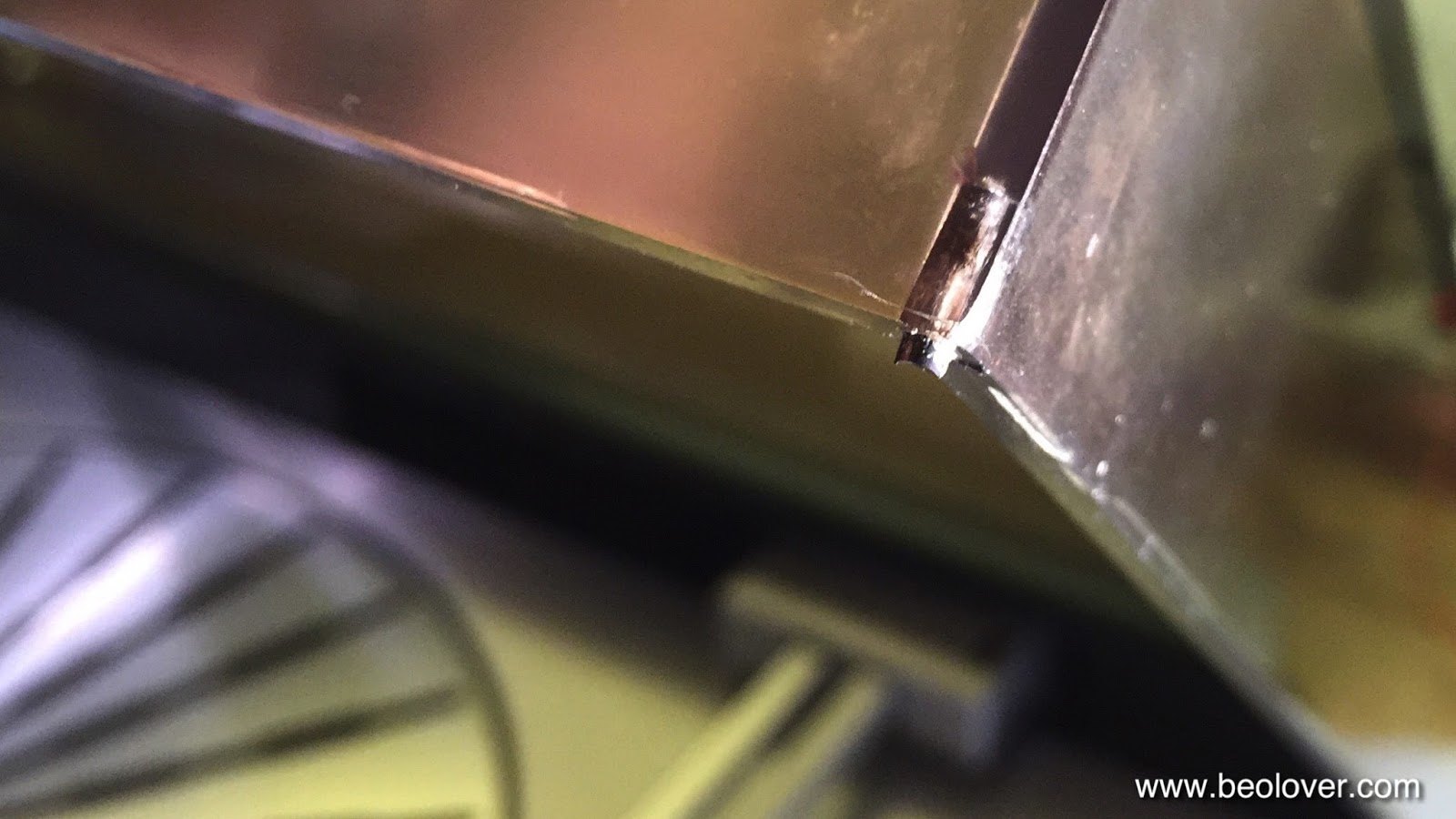
Unfortunately, the keypad has a severely damaged START key, where the coating is worn to the metal surface:
Otherwise the exterior is pretty good, excellent veneer corners, but, unfortunately there is a scratch in the veneer up front:
Maybe this can be sanded/polished out.

Below deck the main damage is fully disintegrated transport lock bushings of the orange type. The orange ones are always crumbling, while the grey ones typically can be left alone. That the transport locks were not engaged did not help this issue since there must have been constant impact on the bushings during the rigors of shipping.

At any rate this is not difficult to fix, and the 400x units are of a pretty rugged all-metal design, which makes permanent shipping damage unlikely even if the locks are not engaged.

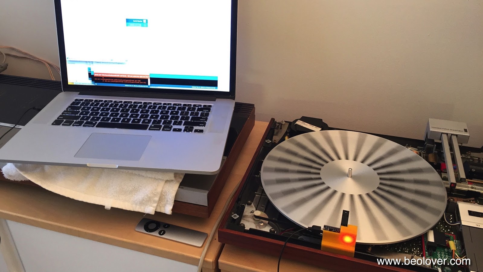
After this cosmetics assessment I looked into the carriage issues that were described to me: I was told that the carriage does not stop at the set-down point after activating START. I plugged in and did a test drive, and indeed the carriage continued running towards the center even with platter absent (in this case the control system comes to the conclusion that a record is present since there is no reflective surface). However, the solenoid engaged at the correct 30 cm point. This immediately told me that the mechanism is working, but that the tracking sensor needs adjustment. Indeed, moving the tonearm to the right with a finger immediately stopped the erratic forward motion. So this will be an easy fix. I also noticed that the arm mechanism is a bit stiff due to hardened lubricants, i.e. this needs some attention to achieve smooth operation.
I also noticed that the DC motor runs a bit rough. This is an indication that it needs some lubrication of its sleeve bearings and a cleaning of the commutator and the brushes.

The bottom line on this Beogram is that it is a nice starting point for a restoration. Nothing abnormal considering the age. I am confident it can be brought back up to specifications.

Tuesday, December 22, 2015

Beogram 4002 (5513): A New Arrival - A First Look!

Another Beogram 4002 (5513) arrived recently. After an unplanned (yet interesting) delay with the Beogram 4000 that I recently rebuilt, it was time to have a look. I extracted it from the double box where an excellent packing job had prevented any shipping damage. A detailed video about how to do pack a Beogram properly is shown here.

Once I had it out, I took the hood off and had a look at the panels:

They are in very nice condition. The keypad shows the usual triple digit usage pattern indicating not too heavy use:

The STOP key is a bit pulled up, but not too bad. Then I had a look under the hood:

Everything looks quite nice...no obvious signs of 'human intervention' (usually the most challenging  and interesting repairs result from that...;-) and pretty clean. Also the transport lock bushings are still good, so there was no need to put the vacuum cleaner to it. Then it was time to plug it in. I pressed START, and nothing! After checking the fuses, which have corroded holders,

I measured the voltage at the reservoir capacitor, which yielded a healthy >30V reading. After establishing the presence of power, I then determined that P5 had come loose during transport. I plugged it back in and tried again. Now the carriage started limping hesitantly (due to a loose servo belt and hardened lubricants) towards the center of the record. Once it made it to the 30 cm set-down point it properly activated the solenoid, but nothing further happened. Moving the linkages by hand immediately suggested that the lubricants are hardened and that the mechanism needs cleaning and re-lubrication. A first sign of this was the non-parallel tonearm when I had a first look under the hood:

This is usually a sure sign that the arm linkage is stuck. So far so good. It seems mechanically all it needs is a good cleaning and some lubrication to get going again. After this I assembled the panels and put the platter on with the belt to check the platter and arm alignments. As usual the platter sits too low and the arms are not horizontal...this needs to be adjusted.

Other than that the cosmetic condition of this deck is really nice. The hood could use a deep polishing since it has a few deep gashes that can be felt with a fingernail:

One really wonders why people do not put a plastic bag and some foam pad on their Beogram hoods before they store them in their basements. But such is the world. Luckily, there are good polishing materials available these days.
Lastly, I had a look at the MMC20CL cartridge that came with the deck:


The sapphire cantilever and the tip looked pristine and everything appears well-aligned. So I stuck it on the Beogram 4000 that I am re-testing again before shipping, and put Eberhart Weber's "Fluid Rustle" on a pristine ECM pressing that I recently obtained from ebay and cranked up the volume on my Beomaster 6000 4-Channel. Absolutely gorgeous! This cartridge seems to be in pretty good condition!
So, the bottom line is that this is a very good starting point for a happy Beogram 4002 restoration! The deck is in a great cosmetic condition, which is usually the most important concern when it comes to investing money into a restoration. 


Beogram 4000: End Groove Detection Issue

After polishing the hood I thought I was done with this Beogram 4000, but not so. A last full performance check before boxing it up revealed a strange fault when ON was pressed with no record on the platter. The carriage would properly travel inwards in search of a record, but then before hitting the end switch ES the carriage would suddenly stop. Only pressing FF would release it from this state. However, then after letting the FF key go the carriage would immediately travel back without even touching the ES. In a healthy state the carriage should travel until the ES is activated and then it should return to the home position.
A closer look revealed that the carriage stopped right when it closed the MV switch that enables the end groove detection mechanism. Here is the relevant section of the circuit diagram:

Here is how it works: Whenever the MV switch is activated by the slide, MV' and MV are connected in the diagram. This puts part of the voltage on the motor across BE of TR24. So whenever the motor revs a bit higher, such as when the needle enters the end groove, the transistors 24/23/22 are activated and DS finally goes LOW. This tells the control system that it is time to lift the arm and drive the carriage home. Now this mechanism is of course only useful when the needle is on the record and entering the end groove. When the arm is up and the carriage is driven forward or backward this mechanism needs to be disabled. This is achieved via D4 which feeds the collector of TR25 into the base of TR23. 
The collector can only be high if FF is activated either by pressing the key or via Q0' which is LOW whenever the carriage is driven towards the center of the record after pressing ON. The tracking mechanism does not use TR25 since it directly goes into TR27/28, i.e. end groove detection is not disabled if the carriage tracks normally.

Further tests of the matter revealed that Q0' remained LOW even as the carriage stopped. This told me that the control system was still of the opinion that the carriage should move, hence the fault needed to be on the executive side of the system, i.e. right here in the MV circuit. I measured D4 from the back of the installed main PCB and promptly saw that it was open circuit, which killed the deactivation mechanism, and the end groove detection mechanism was active even with the arm up. After turing the board around I saw that the diode was cracked in half:

The original OA90 diode is a Germanium diode, but can easily be replaced with a modern 1N4148 Si signal diode since its only function is to block any voltage from the MV circuit to apply to the collector of TR25. Here is a picture of the 4148 installed:

After this I replaced the board and gave the deck a test drive. All good again. Listening to Walt Dickerson's "To My Queen" while I write this, which is definitely one of my all time jazz favorites. O.k. maybe now it is time to finally send this 4000 back to its owner.