Everything is back into the chassis and now it's time to do a last check of all the wiring and powering up. It's important to make sure that no wires have been cracked, became loose or touching the chassis. This may seems obvious, but it is so important in a Beomaster 6000 quad because the space is so tight and most wiring is done with hard wires. I took all the time that I needed and found one wire broken off: a ground connection to the pre-amp.
So, a last peek inside before powering up......


I plugged the unit into my Variac transformer, gently raised the voltage to the required 230V and...........it fired up on all engines! I selected a FM station and listened to Katie Melua's version of Louis Armstrongs "What a wonderful world" ! And indeed it was......
That was a big relief. You never know what will happen after such a big restoration. But, off course, I had tested everything already before putting it al in the main chassis (check here).
Some final calibration was now needed. I started with the power supply. I had done this before when restoring the power supply PCB, but under load settings may change. I found some slight variation. The +18V had now dropped to +17,85. Not to bad. And the -5V was now -5,1V (not sure why it went up). With the new trimmers in place, it was easy to recalibrate to the correct voltages.


On the same power supply PCB, a trimmer is located to balance the FM reception lights.
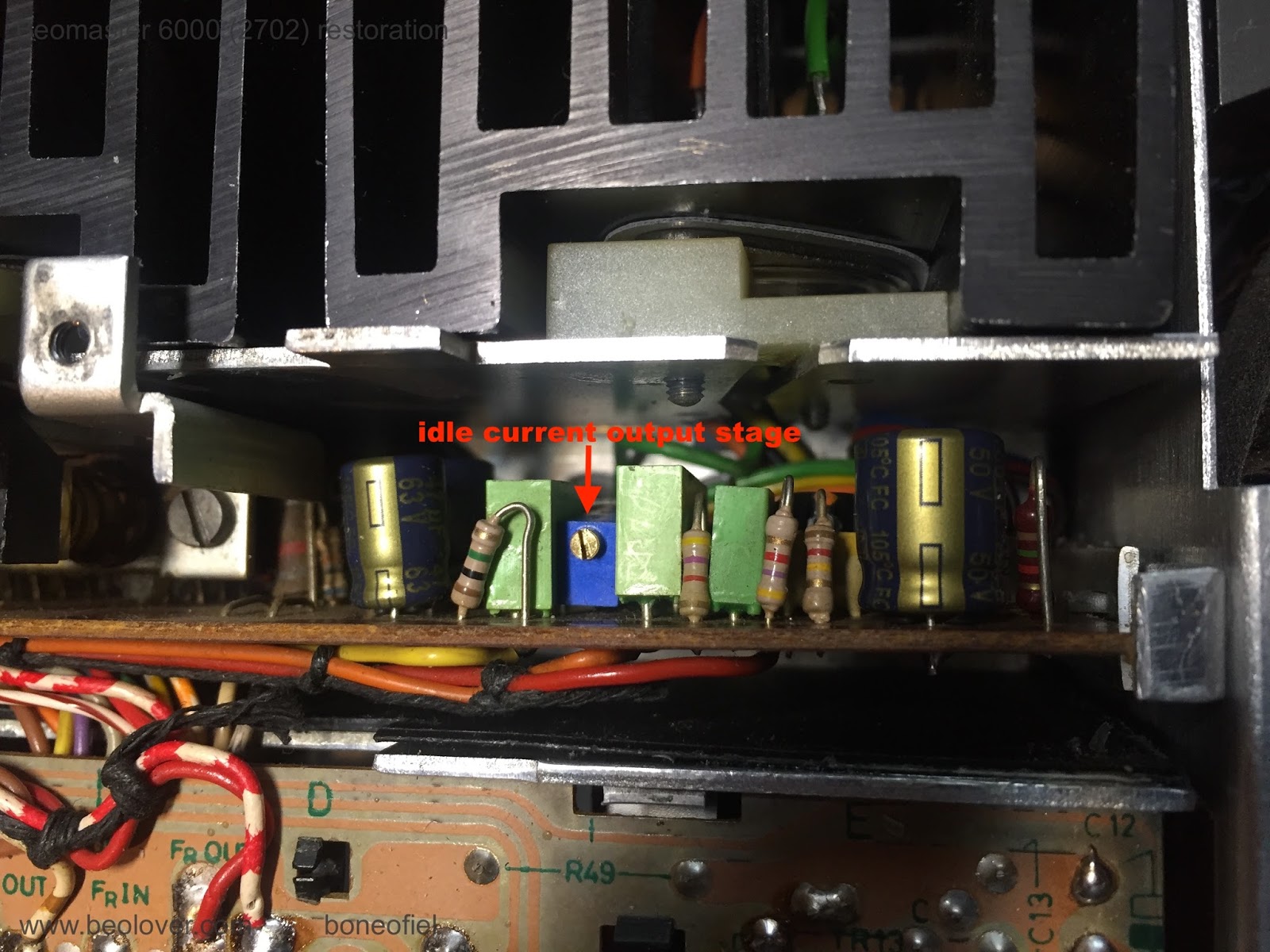
The idle (quiescent, bias or no-signal) current was already set before, but I checked it again by measuring the voltage drop over the 2 emitter transistors (0,12 ohm), in series, that are in each set of the Darlington output stages. The service manual describes to measure directly on one of the collector resistors on the PCB. They are very difficult (if not impossible) to reach once the PCB is in place in the subframe. The easiest way is to measure directly on the emitter contacts of both Darlington transistors (PNP and NPN pair) on the cooling elements (white & green wires in below picture). The correct setting in this case is 14,4mV (2x7,2mV). The extra base-emitter current that flows through the emitter resistors together with the collector-emitter current, is neglectable.


Next was the FM bottom voltage adjustment. The manual describes +4,5V. The FM tuner is driven by a variable DC voltage and to make sure that lowest FM frequency is correct and corresponds with the display, this bottom voltage needs to be set correctly.


Another series of adjustment are related to the FM display board with the signal strength meter, the stereo light and the tuning balance lights.


Other calibrations (like the ultrasonic receiver and the Commander remote) have been done before (see here).
Up next is the mounting of the FM display scale and fixing a new dial cord.
No comments:
Post a Comment
Comments and suggestions are welcome!