Featured Post

Beolover SyncDrive: DC Platter Motor Replacement for Beogram 4002 and 4004 (Type 551x and 552x)

Late Beogram 4002 and the 4004 (Types 551x and 552x), which have DC platter motors instead of the earlier synchronous AC motors usually suff...

Monday, December 7, 2015

Beogram 4000: Adjusting the Tracking Force and Replacing the Strange Original Front Center Cabinet Guiding Washer

The Beogram 4000 that I just finished up is now running smoothly. I am playing 'Song for My Father' by Horace Silver (unfortunately a reissue, since the original first pressings are unaffordable these days...sigh!!), which is one of my favorite jazz tunes while writing this post.
Before I got here, however, I still had to do a bit of work on this Beogram: Adjusting the tone arm weight and limits. I also replace the strange standard guiding washer that is typically found installed in the front center guiding slot to ensure a straight movement of the plinth when it is pushed back to secure the aluminum panels. Here is a picture of the original washer including the shoulder bolt:


This awkward setup just does not work well, and consequently later Beogram 400x have a much better design based on an eccentric washer shape. I recently designed 3D printed replicas of this design since they often crack in 4002 and 4004 models that are outfitted with plastic versions of it. See this video for their installation. The parts are available via my Shapeways store (five washers are needed to replace all of them).

Here is a picture of the new washer installed together with a new M3 bolt (note the much lower profile of the assembly, which is beneficial when installing the aluminum panels as chafing is avoided):


After this small detail, I did the arm adjustment. Most important are the zero weight and tracking force calibration and the proper adjustment of the arm lowering limit, which can be the final stop gap that keeps the platter from ripping the needle out of the MMC cartridge in case of a failing photosensor or misadjusted sensor bulb. Earlier I posted videos about these two procedures (tracking force calibration, arm lowering limit). Equally important is the improvement of the weight adjustment screw assembly, which I usually upgrade with a M3 nut and washer. This allows to permanently fix the adjustment in place, which is critical for a successful out-of-the-box setup when I send the turntable back to Italy. The original setup with the locking washer is too flimsy, which can result in a change of the calibration during shipment. Here is a picture of the installed nut:

And here the needle on the tracking force gauge at 1g after adjusting everything:

Ah...Horace Silver via a perfectly adjusted 4000 and my Beomaster 6000 4-Channel - perfect pairings!...I am in Beoheaven..;-)


Beogram 4002 (5521): Replacing the Deteriorated Transport Lock Bushings

The Beogram 4002 that I am restoring right now came with decayed transport lock bushings. A tell tale sign of this issue is the random distribution of small orangish plastic fragments throughout the enclosure after shipping.

A while ago I designed 3D printed replacement bushings that can conveniently be inserted with the sub-chassis in place. This is achieved through the use of two halves that can be installed from the top and from below. Here is a picture of the parts:

If you are interested they are available via my Shapeways store. Each bushing requires two of the parts. A video about the installation process is posted here. It is important to not confuse the upper and lower brackets of the lock assembly since they have opposite threads, i.e. it is best to mark the top one before taking it out to get at the bushings.

Here are a few impressions of restoring the bushings in this particular unit. This shows the cracked original bushing of the lock at the front:

This shows the lower half of the replacement bushing inserted into the cleaned up opening:

And here a picture after inserting the top half.

I did that for the other two, too. A bit of cleanup of the fragments with a computer vacuum, and all was good again!


Saturday, December 5, 2015

Beogram 4002 (5521): Replacing the RPM Scale Illumination Bulbs with SMD LEDs

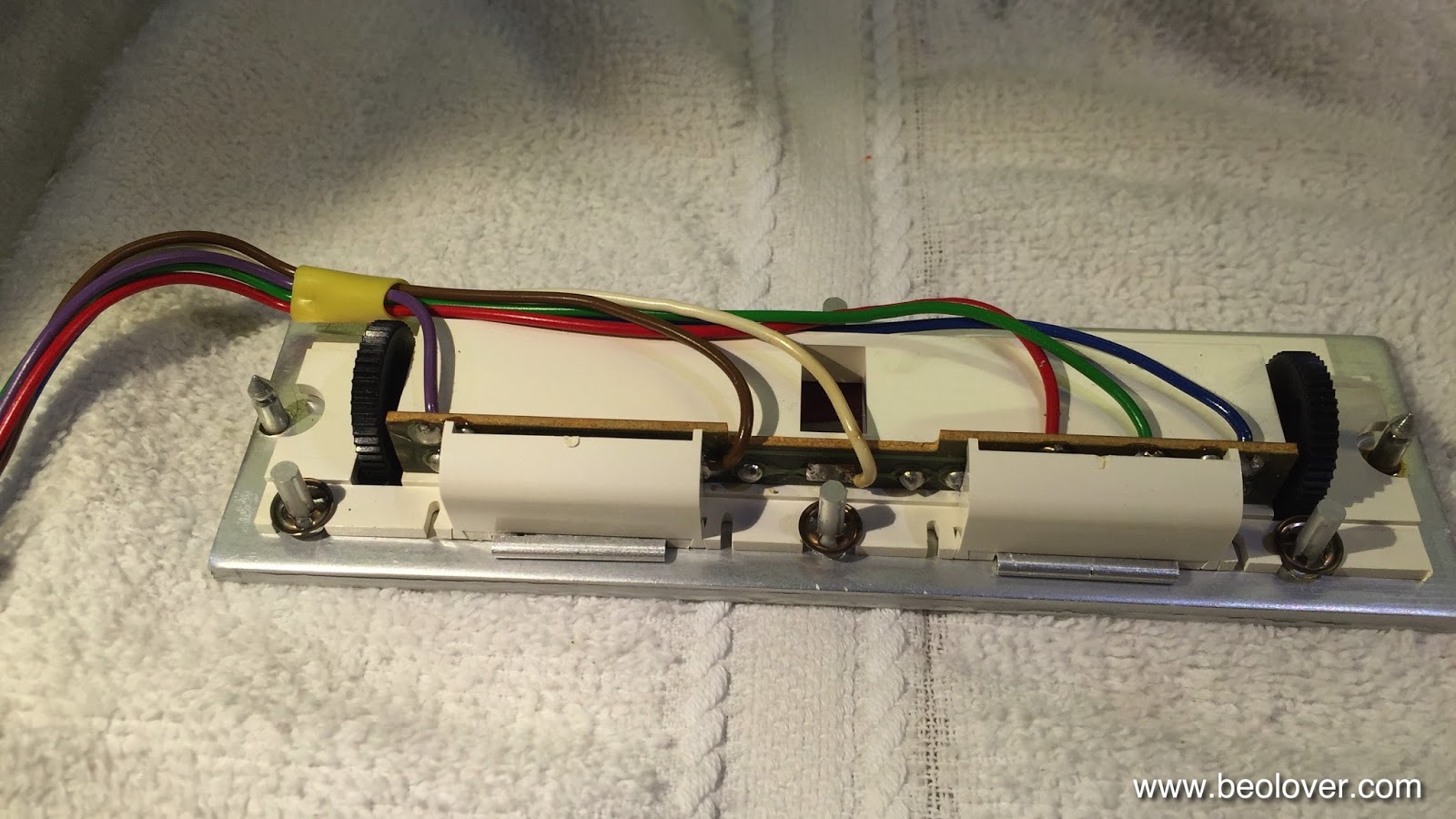
After replacing the broken light source of the tracking sensor, The next step of my current Beogram 4002 (5521) restoration was to replace the incandescent light bulbs in the RPM trimmer panel. The 33 RPM bulb was burned out, so we decided to replace both bulbs with my drop-in SMD LED assemblies. I am using red-green LEDs to ensure that there is a red light component to ensure proper illumination of the red RPM indicators. While amber LEDs can result in an incandescent-like look, they are not able to properly illuminate red surfaces due to their narrow wavelength distribution. Here is a picture of the small circuit boards that carry the LEDs as well as two current limiting resistors, one for the red and one for the green LEDs. This allows to tune the relative intensities to achieve an authentic looking illumination:

I recently made a video that shows how to exchange the bulbs with these boards. They are available to other enthusiasts. Just send me an email. 

Here are a few impressions of the installation in this particular Beogram. This shows the trimmer panel after removal:

The bulbs can be accessed after removing the two covers:

After unsoldering the leads the bulb assemblies can be slid out:

Now the PCBs can be installed. It is important that they sit flush with the aluminum surface:

And then the covers can be replaced:

And that is it!


Beogram 4002 (5521): Replacing the Tracking Sensor Light Bulb with a SMD LED

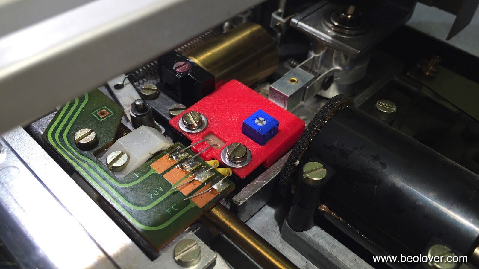
The Beogram 4002 that is on my bench right now came with a broken tracking sensor light bulb. I replaced the bulb housing assembly with my SMD LED based drop-in ready replacement part. This unit was recently redesigned on the occasion of a Beogram 4000 restoration to feature an integrated intensity trimmer, which makes the adjustment of the tracking sensor feedback much more straight forward. The trimmer allows to fine-tune the feedback after the mechanical positioning of the light sensors below the light source. The adjustment process is discussed in detail in this video. 

This shows the original setup of the tracking sensor:


Here is a picture of the latest iteration of my design in comparison with the original bulb assembly after I removed it from the tracking sensor:

This part is available to other B&O enthusiasts. Just send me an email.

This shows the installed part:

Once the LED assembly was soldered in, I performed the adjustment procedure as shown in my video to achieve that the carriage motor starts advancing after 2±1 rotations of the record after lowering the needle onto the record. This restored the basic functionality of this Beogram. On to replacing the RPM light bulbs with LED assemblies.


Wednesday, December 2, 2015

Beogram 8000: Replacing the Carriage Belt

Another loose end in the Beogram 8000 that I am readying for shipping I needed to attend to: I earlier noticed that the carriage belt was quite loose, i.e. at the end of its lifetime. On the occasion of my recent effort to replace a cracked BUNA-N volume belt in a Beomaster 6000 I ordered samples of the entire lineup of EPDM 1/16 O-rings at the O-Ring Store with the goal to be ready for future belt replacements of yet unknown diameters. So I thought I probably had the proper EPDM ring for the Beogram 8000 already in stock! And indeed: It turned out that the E70025 (1-3/16" diameter) ring made a good replacement of the original belt. Here are a couple of impressions:

This shows the original belt with rotary encoder sensor cluster removed (just pull the plastic clamp out and carefully pull the board up while making sure that the IR emitter passes through a gap in the encoder wheel), which is necessary to get the belts over the encoder wheel:

And here after installing the new belt:

It is interesting to note that my first attempt with a 1-1/16" belt did not work out. When I checked initially the carriage would move very well with it. However after attempting to play a record, it turned out that the Beogram would have trouble to move the arm to the run-in groove.

What happened was that the firmware in the microcontroller reduces the power on the carriage motor before the touch-down point to get a more precise positioning (and probably also because it just looks more elegant...;-). However this is apparently not done via encoder feedback but rather via a blind  flight power reduction without monitoring the encoder action. This resulted in a very slow movement of the arm do to the unexpected friction caused by the too-tight belt. It would take several seconds from moving swiftly near the position and then via a very slow final movement to the touch-down position. Replacing the ring with the 1-3/16 version cured this issue and now it behaves like with the original ring. All good now under the hood! Playing right now my just arrived 180g reissue of Queen's 'A Day at the Races' - those were the days!...;-)


Beogram 4002 (5521): Rebuilding the DC Motor

I started working on the Beogram 4002 that recently arrived. When doing my initial assessment, I noticed that the DC motor has completely dry sleeve bearings and so every time it would turn on without the belt and platter installed, it would emit a shrill noise due to the high RPM without a load. So this had to be fixed first. There must be peace and quiet in the Beolover's lair (and some nice vinyl playing while I do my work...;-). Here are a few pictures taken during the process. this shows the motor in-situ:

After removing the mounting plate, unscrewing the two screws that hold the motor to it and removing the glued on pulley (this may require some carefully administered force with a large screw driver to pry it off), I opened up the outer enclosure and extracted the motor:

Then I opened the motor up by removing the bottom shell that contains the brushes and the feedback coils:

Nice classic design! Then I extracted the rotor after removing all glue remnants on the shaft (this is important since otherwise the shaft gets stuck in the upper sleeve bearing and then damage can ensue:

Once at this point, all that is needed is to clean the commutator and the brushes with a fiberglass pen, lubricate both bearings with some silicone grease and then put everything back together in reverse. Note that it is crucial to make sure that both brushes are fully inserted onto the commutator before closing the motor back up. The pulley needs to be glued back on, too. Super Glue Gel works nicely. 

I did all that and installed the motor, and now it spins very quietly. Time to enjoy some vinyl! (just ordered an original 70s pressing of Miles Davis' "E.S.P", one of my favorite jazz records of all time)! - let's see if my vinyl record cleaner can salvage it...I really started liking using it...;-)


Beogram 8000: Installation of New Rubber Bumpers on the Hood and Beneath the Aluminum Lid

I still have a few odds and ends to clear up on the Beogram 8000 that I recently restored. While it is now playing nicely and all functions are restored, the hood was still missing its rubber bumpers and so did the aluminum lid. These rubber parts decay over time and then they break off. But they are important to give the user the correct feel and sound when letting the hood or the lid close on their own. I have not seen a 8000 that still has all of them. Luckily, my own 8000 still had an original one, so I was able to take some measurements. Since these bumpers are not available anywhere, I resorted to using a 1/16" rubber sheet and double sided tape to repair the one under the aluminum lid. The bumpers on the hood cannot be fixed that way, but a piece of .1" O-ring does the job...see below.

Here is a picture of the small cavity that holds the bumper under the lid: 

This shows the hole punched pieces with the double sided tape on them:

I found that a 3/16 punch generates perfectly fitting bumpers:

Pretty! On to the hood. This shows the missing bumpers on the right side:

And with the 0.1" O-ring section forced in but still too long:

To get the precise 1mm height of the bumper, I 3D printed myself a mask for cutting the rubber segments off in parallel to the hood edge with a razor blade:

This picture shows the fit of the hood after cutting the rubber segments off:

Perfect alignment with the control cluster. This is Beolove!