Featured Post

Beolover SyncDrive: DC Platter Motor Replacement for Beogram 4002 and 4004 (Type 551x and 552x)

Late Beogram 4002 and the 4004 (Types 551x and 552x), which have DC platter motors instead of the earlier synchronous AC motors usually suff...

Saturday, May 26, 2018

Beogram 4004 (5526): Final Adjustments and Test Drive with Volker Kriegel on MPS

My current Beogram 4004 (5526) restoration project is coming to a close with making a few essential adjustments and tying up some loose ends. First, I replaced the original black plastic carriage pulley with a new one machined from aluminum:

Then I replaced the metal sheet screw that holds the tracking aperture in place
with a nice stainless steel 2 mm bolt that can be tightened with a ball hex key...much better than the original Philips head to get it fully tightened to survive the rigors of shipping in the calibrated position. This shows the new bolt in place:
Then it was time to adjust the tracking feedback sensitivity:
The intensity adjust trimmer (small blue box) on the Beolover tracking sensor light source comes in handy for fine-tuning the mechanism after coarse adjustment of the aperture and sensor positions.

Then I adjusted the floating sub-chassis to be horizontal, did the arm to platter distance adjustment while making sure that the platter is flush with the surrounding aluminum panel. Then it was time to adjust the arm lowering limit that the needle would miss the ribs if it got accidentally lowered onto the platter without a record present. An important fail safe in case the record detection mechanism fails at some point in the future:

Before playing any turntable for the first time it is important to calibrate the tracking weight. I usually start out by replacing the flimsy locking clip that holds the counter weight adjustment screw in place with a nut to be able securing it permanently once the calibration is done. This shows the original condition:
and with the M3 nut in place:
Then I calibrated the weight adjustment wheel to be accurate around 1.2g, the tracking weight for most B&O cartridges:
This is preferably done with a small digital gauge, which are very precise these days due to advances in integrated sensor chip design (even if they are cheap).

After giving the aluminum surfaces a deep clean it was finally time to present this Beogram in its full glory and play it for the first time. I selected a recently acquired vinyl by the awesome German MPS label: "October Variations" by Volker Kriegel and the Mild Maniac Orchestra, which they recorded in 1977.
In my opinion this is among Kriegel's best albums for its consistency and wealth of great melodies and jazzy fusion sound. The second track on the first side "Ballad Garden & Palm Dreams" is my favorite...perfect for taking a Beogram DC motor apart or soldering SMD components...;-). I will now play this Beogram for a bit longer, and then it will be time for the trip home to its owner.


Friday, May 25, 2018

Beogram 4002: Restoration of a Very Oily DC Platter Motor

I recently received a Beogram 4002 DC platter motor from Berlin, Germany for restoration. I immediately noticed that the motor was quite oily on the outside, probably from an attempt to lubricate it to enhance RPM stability. This shows the motor as received:
I disassembled it to extract the bearings for oil infusion:
The bearings are on the black pad up front. The inside of the motor was also very oily, but of course this does not help the bearings, since they need to be infused with oil under vacuum. This is necessary to pull out the air in the pores of the Oilite brass material that the new oil can penetrate into the bearing. This shows the bearings submerged in motor oil after pulling a vacuum:
The bubbles rising from them is the air exiting the bearing. This process usually takes 24-72 hrs depending on the state of the bearings.
After the bubbling stopped I extracted the bearings from the oil and put them on a paper towel to wick the excess oil away:
Then I re-assembled the motor again and implanted it into one of my 4002s. Then I ran a 24 hrs RPM stability test with the BeoloverRPM device, which allows the logging of the RPM for extended periods of time:
The BeoloverRPM is available to other enthusiasts. Just send me an email or use the contact form on the right. The very unstable blue curve on the graph below is what I measured:
This indicated that I was not done yet with this motor. First I thought the motor probably needed new spark suppressors since that usually causes large downward spikes, but the overall pattern looked somewhat different. Finally, I remembered that I had a similar issue when I just started developing the restoration procedure for these motors a few years back. Initially, I also thought that simply putting a lot of oil in everything would probably help. But when I squirted some of the oil on the commutator of the motor (to 'further reduce friction'...;-), the motor performance dramatically worsened, like in this case. It seems that the oil creates an insulating layer on the rotor impeding the current flow though the rotor, which causes RPM reductions.
So I took the motor apart again and cleaned rotor and brush carrier (together with the pulley - it was also oily and I worried that I would not be able to glue it to the shaft once done) in my ultrasonic cleaner:
I put it in warm water with some dish washing detergent. Immediately after starting the cleaner the water became very cloudy.
This indicated that an emulsion was forming between the oil on the parts and the water. I replaced the water three times and ran the cleaner a couple minutes in each batch. Then the water finally stayed clear and I gave it a fifth run in pure ethanol to get the water out of the rotor windings etc...The I put everything out for drying:
After re-assembling, I tested the motor for another 24 hrs and I was able to measure the nice red curve in the above graph. So everything is fine now with this motor, and it is ready for return shipping to Berlin!

Thursday, May 24, 2018

Beogram 4004 (5526): Installation of A New Output Cable

After replacing the light bulb in the sensor arm with an LED assembly it was time to look into the RCA plug 'conversion' of this Beogram 4004 (5526). This shows the output cable in the condition when I received this Beogram:
Not a very inspiring sight. The blue and yellow leads are the Beolink signal lines that allow controlling the 4004 via a Beomaster 2400. We decided to return this 4004 to its original DIN7 output scheme. Originally the 4004 came with a convertible male DIN7 plug, which can be turned into a standard DIN5 by unscrewing the two pins that are extra in the DIN7 format. This shows a plug as seen on a 4004 I restored a few years ago:
The two outer pins were removed so that the plug essentially acted like a standard DIN5 phono output. Unfortunately, such DIN7 plugs are not available anymore. A solution I came up with is to install female DIN7 plug that has all the signals on it. If extended with a DIN7 cable it turns into a DIN7 male output that will properly work with a Beomaster 2400. Extend it with a DIN5 or a DIN5-to-RCA adapter and a standard non-B&O phono output is achieved.
This shows the female DIN7 plug during the installation:
Note that the leads need to be soldered in a mirrored pattern compared to that applied for a male DIN7 plug, since male-male DIN5 and DIN5-RCA jumper cables mirror the leads for symmetry reasons.

This shows the DIN7 connected to a DIN5-to-RCA jumper cable:
The system ground connection is on a separate wire (not visible on this photo) that it can be connected to the GND terminal of the RCA input amplifier.


Beomaster 8000: Wrapping Up The Performance Tests

The current Beomaster 8000 restoration project has been going through quite a bit of testing in the last few weeks. Its owner mentioned that this Beomaster would occasionally come on by itself. Sometimes in the middle of the night it would come out of Standby mode and start playing music. It's always nice to listen to a Beomaster 8000 but you do want it to obey your commands.

I was confident that the restoration work I performed would address that issue but to test it I left the Beomaster plugged in on Standby mode for three full days. No hiccups and it never went into play mode by itself.

It was back to more listening tests while I set up the bench for some performance tests.

As Beolover recently posted, we don't really have the specific test information and test equipment that Bang & Olufsen used when they tested these Beomaster 8000 amplifiers with respect to what is in their technical specifications. On amplifiers there are usually only two service manual adjustments. No-load current (idle current) and DC Offset. That is the case with the Beomaster 8000. Other than those two adjustments a restored amplifier is expected to perform at the manufacturer listed specs for their design. We can use their published specifications as a guide as we collect our own measurements using test equipment available to us today. With these new measurements we will have measurable and repeatable values to compare our amplifier restorations.

Both Beolover and I use the QuantAsylum QA400 Audio Analyzer to make measurements. We also both use 8Ω fixed loads (power resistors mounted to large heatsinks) as dummy speaker loads during the tests. A small 0.08Ω to 0.1Ω resistor is added in series on each speaker load to allow direct measurements to the QA400 analyzer.  That is because the full voltage across the 8Ω load would damage the analyzer inputs. I have a pair of  QuantAsylum QA190 low noise, differential probes that allow measuring directly across the 8Ω (actually 8.08Ω in my case) dummy load. It should be noted that the updated QuantAsylum QA401 analyzer has built in differential inputs so the external probes are no longer necessary.

Here are some pictures of my test setup.


To run a direct measurement to the QA400 analyzer inputs from the 0.08Ω series resistor I use a coax cable with BNC connections for the analyzer and mini-grabbers for the 0.08Ω resistor.


Here is the Beomaster under test with the QA400 analyzer in the background and its measurement screen on my lab computer.


The QA400 analyzer, as described in Beolover's post, outputs a tone burst test signal for single frequency stimulus tests and a square wave impulse for frequency response test stimulus. I can run both left and right channel measurements at the same time as the analyzer provides the input to the Beomaster Tape 1 or Tape 2 left & right channel source inputs.

This test setup is easy to use and I can connect a bench DMM to the speaker loads to measure the actual voltage put out by the Beomaster output amplifier. One problem I run into is occasional noise that mucks with the measurement device sometimes. Usually down at the line 60Hz frequency. In my test setup the direct measurements across my 0.08Ω series resistor just don't provide as clean a measurement as the QA190 differential probes. I also have to monitor the QA190 probes though as they are battery powered (so the batteries need to be fresh).

For these Beomaster 8000 performance tests I decided to first grab a THD measurement for a 1KHz input signal right before it goes to the Beomaster Output Amplifier board. The audio signal goes from the input source (Tape 1 or 2) through the Preamplifier then to the Filter & Tone Control board. The path from the Filter & Tone Control board to the Output Amplifier is via connector 4P24. For this low voltage test I did use some direct probes with alligator clips to the QA400 inputs and not the QA190 probes. That is because of the space available to connect probes to.

Here is the THD measurement for a 1KHz input signal at 4P24.


The left and right channel THD is very low after going through all of the preamplifier and tone control circuitry.  Though it is very low (nearly -100dB) you can see the effect of some 60Hz noise picked up by the measurement cable.

Next was the 1KHz signal THD measurement after the Output Amplifier. This is measured across the 8.08Ω fixed speaker load at different output levels. It should be noted that during these tests I took the opportunity to calibrate the Tape 1 and Tape 2 input level trimmers again so I could make sure they are equal. I also tried to set them where I could set the Beomaster volume control on a level that produces 100W across the 8.08Ω load.  The result of that is a Beomaster volume level of 5.4 producing my 100W test output. The next volume level up (5.5) with this setup causes the clipping light to illuminate.

Here are left and right channel THD and SNR measurements at volume levels of 5.4 (~100W) and 5.3 (~67W).  I also turned the analyzer A Weighting mode on as the B&O specs use that.


The next volume level up (5.5) on the Beomaster puts the output amplifier into clipping so THD of 0.01% at the rated maximum power into 8.08Ω is very good. The next volume setting down (5.3) drops the THD to 0.008%.

Next is a check of the Beomaster frequency response. Beolover also describes this measurement with the QA400. I am showing the measurement picture produced by the QA400 measurement software (with a few of my own text comments added). It has frequency markers for three points I wanted to focus on (1KHz, 10KHz and 20KHz).


My results are pretty similar to what Beolover got although it appears the QA190 differential probes helped my measurements out on the low frequency noise. The drop at 20KHz was right around 1dB which is more than what the B&O published specs state but then our measurement methods are not exactly the same. Between these Beomaster performance results and the last few we have done it compares with very similar results. The results are definitely a pass for this Beomaster receiver.


Tuesday, May 22, 2018

Beogram 4002 DC Motor Restoration

A repair shop in California recently sent me a DC platter motor of a Beogram 4002 for restoration. This shows the motor as received:
I took it apart to extract the bearings which always need oil infusion under vacuum since after almost 40 years they are usually running dry. This shows the disassembled motor:
The two small donuts on the black pad are the bearings. I immersed them in motor oil and pulled a vacuum. Immediately vigorous bubbling started:
This indicates that air is drawn from the pores in the Oilite bearing material making room for oil to diffuse inside. After about 48 hours this process stopped and no more bubbles were visible. I reassembled the motor and put it into one of my Beogram 4002s for a 24 hrs RPM stability test:
This photo shows the BeoloverRPM device which can log the RPM of a Beogram for extended periods of time. This device is available to other enthusiasts. Just send an email or use the contact form on the right if you are interested.
This shows the RPM curve that I graphed after about 24 hrs:
This is as good as it gets for the 4002 DC motor. This motor is ready for duty again. I should mention that this curve was measured with a 10uF value in place for C10 on the main board. This capacitor determines the sensitivity of the feedback based RPM control loop. For some reason a fraction of these motors need a 10uF cap in place, while others benefit from 0.47uF or 0.33uF. This motor tested poorly with a 0.33uF value (which, I was told is also installed on the main board of this Beogram), but yielded the above nice curve with the 10uF value. The joys of analog control systems!...;-)


Saturday, May 19, 2018

Beomaster 6000 (2702) restoration: final assembly and testing

After some delay caused by the need to recoat the key panel (see update here), it is now finally time to finish the assembly and start testing the Beomaster 6000 quad after this full restoration!

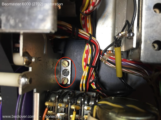
The display panel for the volume, tone and balance controls needs to be as close as possible to the red plexi panel for good readability. Therefore the frame on which the the display panel, motor controls, pulleys, clutches, tone amplifier PCB is mounted is adjustable. On each side on the frame there are 3 M3 bolts:  the middle one is to lock the adjustment and with the two other screws you can tilt and raise the frame.


Since you can not reach these bolts once the plexi panel is back in place, a different method is needed. I first attached the back black frame and the complete key panel to the main chassis. This was to have a reference point for adjusting.


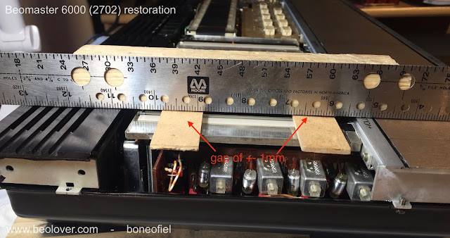
I used a metal ruler and some pieces of wood (with the same thickness as the plexi panel) to make the adjustment.


An air gap of about 1mm is sufficient to leave enough room for the display bands to move freely and avoid rubbing.


Once this is done the keypanel temporary screws are removed and the plexi panel is put in place. The next step is to attach the wood plinth and the keypanel.


One last adjustment, before tightening the keypanel and the wood plinth, is the centering of the FM dial spindle/flywheel. This is needed because the keypanel had been removed for coating and glued back. There is always a bit of play. The spindle is rotating in two ball bearings. The top one is fixed in the square plastic holder just under the spindle. The square plate first need to be centered by loosening the 4 M3 nuts.


The second ball bearing is inside the shaft bushing at the bottom. This ball bearing is in a metal bushing that is adjustable with 3 bolts. If you loosen these 3 bolts the whole spindle can "wobble" a bit and allows to have the spindle surface flat and centered with the surrounding aluminium frame. This can only be done once the keypanel with the wood plinth is firmly fixed.


And finally the wire bracket is put in place.


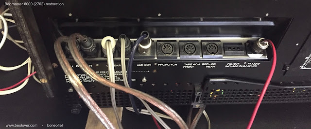
Time for testing ! I attached 2 Beovox S45-2 as front speakers and 2 Beovox P45 as rear speakers. I also attached an Airplay device to play some music from my iPad.


And I had sound on all 4 speakers !!!!! 


A reflexion after this many, many hours of careful restoration of this iconic Beomaster 6000 quad: it's not a job for the faint of heart ! Was it a succes? Yes, definitely. Does it look and sound good? It sounds sweet to my ears. And it looks as good as one can imagine after some 40+ years of use. I've been at the Bang & Olufsen museum in Struer, Denmark, where there is (off course) one of these units on display (and fully operational). See picture below. And honestly, mine looks better ! 

I will now let it play for some days/weeks before I'll ship it to his new owner. 


Above picture is courtesy of the B&O Museum in Struer, Denmark.

Friday, May 18, 2018

Beogram 4004 (5526): Replacing the Light Bulb in the Sensor Arm with a LED Assembly

After replacing the transport lock bushings in the Beogram 4004 (5526) that is currently on my bench it was time to replace the light bulb in the sensor arm with a LED-based assembly. This shows the small bulb compartment pulled out of the sensor arm front:
The small flexPCB next to it is the LED circuit. Since modern high output LEDs have a much lower current draw than the original small light bulbs the LED circuit features a current bypass that adjusts the current to a level similar to the light bulb. This is important since there is a circuit on the main PCB that detects bulb malfunctions via current measurement, and the low current of LEDs would trigger this circuit, preventing the arm lowering mechanism from doing its job.

The flexPCB needs to be folded to fit into the bulb compartment. This shows the folded board next to the light bulb,
and installed in the compartment:
After replacing the compartment in the arm I tested the setup:
The B&O logo shows up with its usual red-orange glow. This is a result of using a warm white LED, which has enough red emission to properly illuminate the logo. The final step of any sensor arm light source replacement is measuring the sensor signal when the platter is spinning without a record on it. This shows the signal measured at the collector of TR3:
Each voltage drop corresponds to a black rib passing under the sensor. When everything is o.k. the drops should go close to 0V, while the amplitude should exceed 4V.  This Beogram 4004 passed the test with flying colors!