Featured Post

Beolover SyncDrive: DC Platter Motor Replacement for Beogram 4002 and 4004 (Type 551x and 552x)

Late Beogram 4002 and the 4004 (Types 551x and 552x), which have DC platter motors instead of the earlier synchronous AC motors usually suff...

Saturday, April 9, 2016

Beogram 4000: RPM Performance Test

I finally did a RPM performance measurement on the Beogram 4000 that I recently restored. I always wondered how the AC motor Beograms perform in comparison to the DC motors, and also the 8000/8002 models with their computer controlled linear motors. So I hooked up my BeoloverRPM device and let the 4000 run for about 12 hours:
This is the curve that I measured:
The AC motor is performing very nicely and the RPM is very stable, but there is some initial drift as the oscillator and the motor warm up. I measured 36C on the motor and 46C on the transformer after the 12 hour run. 

It is interesting to compare the three Beogram platter drives. This graph shows the performance of a Beogram 4002 with DC motor (blue), the 4000 (green) and a 8002 (red) that I recently fixed up:
It is clear that the DC motor 4002 has the largest fluctuations. Interesting is that the linear drive of the 8002 is not significantly better than the AC motor 4000. Of course the computer controlled linear drive does not have the initial temperature drift seen in the 4000. But these measurements show how well-behaved a synchronous AC motor drive can be. The great advantage of this concept is that there is no feedback loop that keeps the RPM constant over time. The AC motor rather follows the driving oscillator, i.e. as long as the oscillator is stable, the AC motor will perform very stable, too. While this is all very interesting, one should not forget that even the DC motor variations are very small, and  that they cannot be noticed while listening to records.


Sunday, April 3, 2016

Beogram 4002 (5513): A First Impression

I started working on another Beogram 4002 (5513). It came in the original box with all the proper packaging materials...very nice! Here are some impressions:
The platter was already taken out when I took this picture....To my shock a pristine MMC20CL cartridge came mounted on the arm...luckily the protective cover was on and being pushed against the styrofoam it stayed in place:
I very carefully removed the styrofoam insert and then took the cartridge out. Luckily it does not seem to have got damaged. The cantilever is centered and intact:
After taking these pictures I played the cartridge on the Beogram 4000 that I recently restored:
And it sounds great! Perfect for Ian Carr's Nucleus' "In Flagrante Delicto", which has some really nice clear trumpet improvisations that deserve the clarity of a MMC20CL!

Then I put it safely away in a Beolover MMC storage container
The lid has a window showing the cartridge labeling:
After this it was time to have a look at the Beogram. The overall cosmetic shape is pretty good, except that the keypad has deep usage damage:
The plinth is also cracked on one corner
but this can be fixed with a bit of glue. Under the hood it is clean and unadulterated:
Then I started it up. It seems to mostly work. the arm lowering mechanism is a bit sluggish but performs its functions and the 33 RPM light is out. Furthermore, the transport lock bushings are gone and the cabinet guiding washers were replaced with standard washers. This needs to be fixed to ensure a proper fit of the top aluminum plates. But all in all, definitely a good starting point for a restoration! 

Since this is a DC motor model, it was time for the BeoloverRPM 24 hrs stability test!
If you are interested in the BeoloverRPM device, it is now available to other enthusiasts who want a precisely RPM-tuned Beogram! See here for more information about this useful gadget.


Saturday, April 2, 2016

Beomaster 4000 (2406): Installation of Custom Designed Toroid Transformer - Final Impressions

I finished up the toroid transformer implantation in the Beomaster 4000 that I am currently restoring. I added a bolt to fix it in its 3D printed cradle and used the mounting plate and rubber shock absorber that came with the toroid to secure it in place. Here is an impression:
Lovely! A very happy look in my opinion! 
Then I put on the bottom plate:
and with plate installed:
This shows a the detail around the 'gills' of the Beomaster:
I like how the red shines through a bit. Since the toroid represents a performance upgrade of the Beomaster and brings its power supply into the current millennium, I like that it can be seen a bit if closely scrutinized. Putting in a toroid into a Beomaster 4000 is a bit like installing Brembo calipers on a vintage BMW 5-series, if you catch my drift...;-):
Toroids have a much improved EMI performance than conventional "EI" style transformers due to their geometry. That is the main reason why most modern low noise analog power supplies employ toroid designs.
While I am writing this post I ran the unit together with the Norwegian Beogram 4000 that I am testing right now, and I can report that it sounds absolutely awesome! No humming on any input and everything stays absolutely cool including the toroid and I am cranking it up quite a bit right now. Appropriate for Jethro Tull's Aqualung!
This pretty much concludes the restoration of this Beomaster (if nothing comes during the testing period). Here is a picture of the units with exchanged parts:


Beogram 4000: Intermittent "17" Position Switch Causing Immediate Touchdown After Launch

After polishing its hood I though I was done with this Beogram 4000. But not so. After playing a few sides out of a sudden the arm lowered next to the platter after I pressed "ON". Not so great. While nothing bad happened to the tip (due to correct adjusted arm lowering limits it did not touch the aluminum panel) this meant that I needed to look into the "17" position switch of the carriage mechanism. This switch is the most problematic one of the position switches since it is the only "break switch", i.e. it is normally closed and arriving at the singles touch down point opens it. See here in the relevant part of the circuit diagram:

If the switch is open, the control system 'thinks' that it has arrived at the 17 cm touchdown point and therefore lowers the arm. So after pressing ON and clearing the SO switch it immediately stops the carriage and lowers the arm.

Being normally closed means that the circuit depends solely on the spring force of the switch tab to be closed which is a weak point of this design. This shows the switches. The 17 switch is the one that does not have a contact terminal across it, i.e. its terminal is underneath the tab and its spring force presses it on the contact terminal:

When I checked on the position switches they looked very nice and unoxidized so I only put a bit of DeoxIT D100 on them and let them be. But I missed that someone prior had 'worked' on the 17 switch and bent the tab thereby reducing the spring force. It is virtually impossible to fix these switches without taking the tabs out, straightening them and then solder them back in. And that is what I did here. This shows the bent tab:
Note the 'bulge' right next to the solder tab and the fairly wide angle between the solder tab and the blade. A clear sign of 'human creativity'. Here is an impression of the bent back into shape tab:
After soldering it back in I started playing the deck again and now everything seems to be smooth. Another demonstration that it is always a good idea to give these old ladies a good spin to make sure everything is stable before shipping them back to their owners! This is Beolove!


Beogram 4002 (5503): Hood Restoration

I polished the hood of the Beogram 4002 (5503) that I have on my bench right now. It also had the usual age conform scratches and chafed areas and so needed a good sanding and polishing back to translucency. Here is an impression of the original state:
The first step as in most cases was sanding with 220 grit paper:
Then it was time to polish it back to a clear state with Micro-Mesh polishing cloth. At the end it looks   clear and happy again:
The job was finished by inserting new rubber bumpers made from cuts of a 2 mm O-ring. This shows one of the original broken off bumpers:
I used a 2 mm drill bit to get the old rubber out and then I glued the O-ring sections in:
After the glue hardened I cut them to size that the hood would sit level on the plinth:
So far so good...the remaining task is to restore the keypad.


Friday, April 1, 2016

Beomaster 4000 (2406): Exchanging the Electrolytic Capacitors and Adjustment of the Quiescent Current

After testing the new toroid transformer for a while (and coming to the conclusion that it works very nicely - no hum in the amplification chain whatsoever) it was time to complete the restoration of this Beomaster 4000 and replace all electrolytic capacitors on the various PCBs with new 105C grade major Japanese manufacturer units. While time consuming, this is not too difficult to do, but a few of the capacitors are challenging to access since the 4000 is from a time when board-to-wire connectors were not commonly used in consumer electronics. In other words, it is difficult to take out boards since most connections are soldered. So it is best to just leave everything in and work your way around a few obstacles like the power switch that obscures a solder point or the vertically installed loudness board. But with a bit of patience, a few tricks and a steady hand it is a straight forward process. Here are a few impressions. The first step is usually to take out the preamplifier board that is directly bolted to the frame with four screws next to the DIN jacks on the back. This picture shows the board in its original state:
And after exchanging the capacitors:
Then it was time to work on the two main boards. Unfortunately the preamp board does not disconnect like in the Beomaster 4400 where a rare wire-to-board header allows this convenience. In the case of the 4000 the board needs to be left connected and dangling from the frame while one works on the main PCBs. But this is not such an issue if one props up the Beomaster vertically using a couple of carpenter clamps affixed to the heatsinks (use cardboard shields to prevent scratches).

This shows the output amplifier board in its original condition:
The four red resistors at the bottom are the emitter resistors that can be used to adjust the quiescent current. In between them are the associated trimmers. I replaced these with modern encapsulated units along with the capacitors. This shows the board after restoration:
Next up was the FM tuner and 15V power supply board. this shows the original condition:
And after rebuilding it:
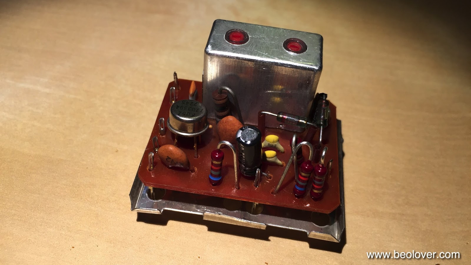
This board has two EMI cans. On the right is the FM 'front end' that selects the right carrier frequency and on the left is the 'detector' that converts the frequency modulation audio information into amplitude change that can be amplified and analyzed into an audible stereo signal. Unfortunately there is one electrolytic capacitor in each can and so one needs to get in there. The easy one is the front end, where the top and bottom covers come off easily. Note that the bottom one has a soldered ground connection which needs to be unsoldered before it can be taken off:
This shows the solder side of the PCB after taking the bottom cover off:
And here is a peek into the top:
The capacitor is in the top part, a brown/black tantalum type. This shows it replaced:
Care needs to be taken to not disturb the inductors. If they get accidentally 'adjusted' one may need a FM signal generator to recover. After putting the covers back on I turned my attention to the detector. Here the board is piggybacked on top of the main FM board and so one has to unsolder it first before the bottom of the PCB can be reached for soldering. The top cover can simply be pulled off. This is how it looks after it is off:
Then I took the board out:
The capacitor is up front center (also brown/black; 10uF). Before one can unsolder it the bottom shield needs to be taken off. One of the pins is soldered into the PCB, making the ground connection, i.e. it needs to be unsoldered first. Then the shield comes off:
And then I was able to put the new capacitor in:
After putting everything back together in reverse I took this picture:
On to the loudness board that is right behind the loudness switch on the front panel. There are two capacitors (red):
I should have replaced them while the transformer was out, but it did not occur to me. So I did some 'artistic soldering'. Copper brain is very useful for such situations when the desolder gun is too big to fit. After a bit of effort I had them out and replaced with new units:
Alright! Almost done. On to the FM preset capacitors that are soldered directly to the preset switches and a ground wire:
I also replaced them with new units:
The next step was to adjust the quiescent current with the new trimmers:
I elected to ignore the prescription of the service manual to measure the current in the output transistors directly with an ampere meter connected into the circuit. The setup allows for that via two pin headers that are not soldered. However, I did to like the idea to connect a multimeter with an internal resistance of about 5 Ohm in mA mode into the circuit and thereby altering the setup. I instead calculated the current that corresponds to the prescribed 80mA quiet current in the 0.15 Ohm emitter resistors in each of the B-style push-pull output branches (12mV), and hooked up my multimeter across these resistors and adjusted the trimmers to get the 12mV. Now this Beomaster is running cool. When it arrived one of the channels got pretty warm indicating trimmer issues, as they are frequently found in this vintage of B&O.