The last remaining board to work on is the display board. I guess I saved the easiest board to remove for the end. It only has two capacitors to replace so it should also be the easiest board to work on. However, the digital displays on this board often begin to have faulty LED segments after thirty five years. On the capacitor replacement we replace all of the electrolytic capacitors regardless if one still measures in spec. The reason for that is we know they can and likely will fail. The same reasoning goes for these displays.
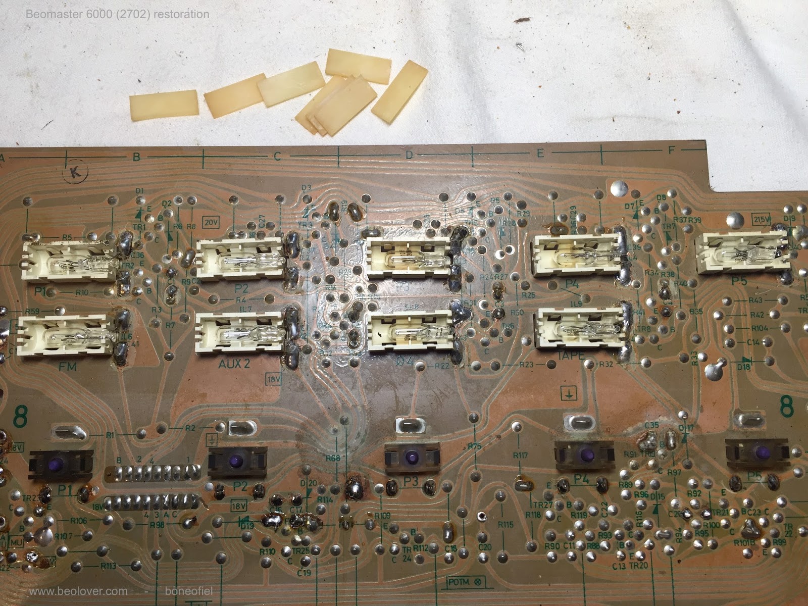
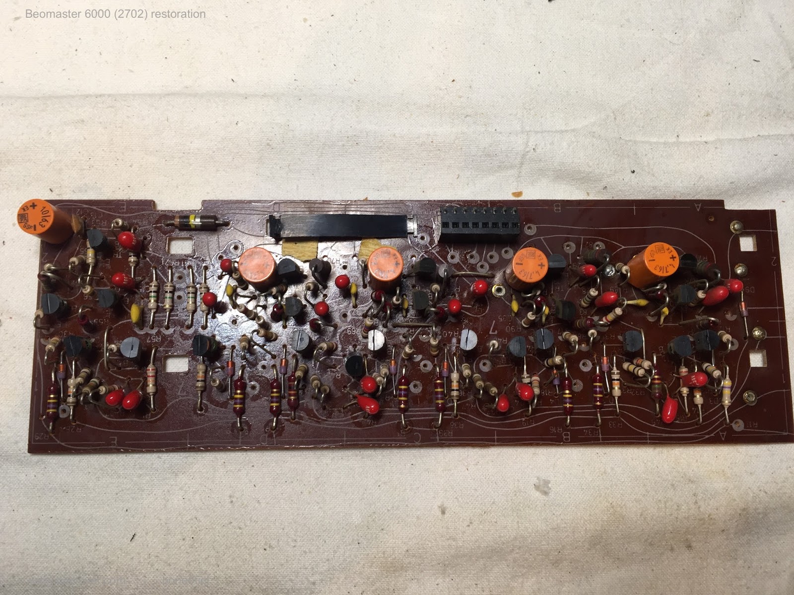
Here is the display board for this Beomaster prior to the restoration.
I removed the four segmented display modules as those are the components with the LEDs that eventually start to fail.
There are also four incandescent bulbs (Clipping, Filters, Mono, Manual tuning) that will get replaced with Beolover LED replacement modules.
Here are the two electrolytic capacitors replaced (a 10uF and a 4.7uF).
Here are the before and after pictures of the incandescent lamp replacement.
Note that four 220Ω resistors (R34, R36, R38 and R40) are removed from the board.
The most time consuming task on this whole Beomaster 8000 project is the replacement of the LED displays. Since several Bang & Olufsen components from this early eighties time period use this type of display I made a test jig for bench testing them.
I always check whether any segments have started to fail or not. It turns out all of the display segments are still functioning on this Beomaster.
Very nice and a key design element to these Beomaster units. However, we would really like to insure that this Beomaster doesn't have to come back to the shop in a year or two if these old display segments finally start to give out.
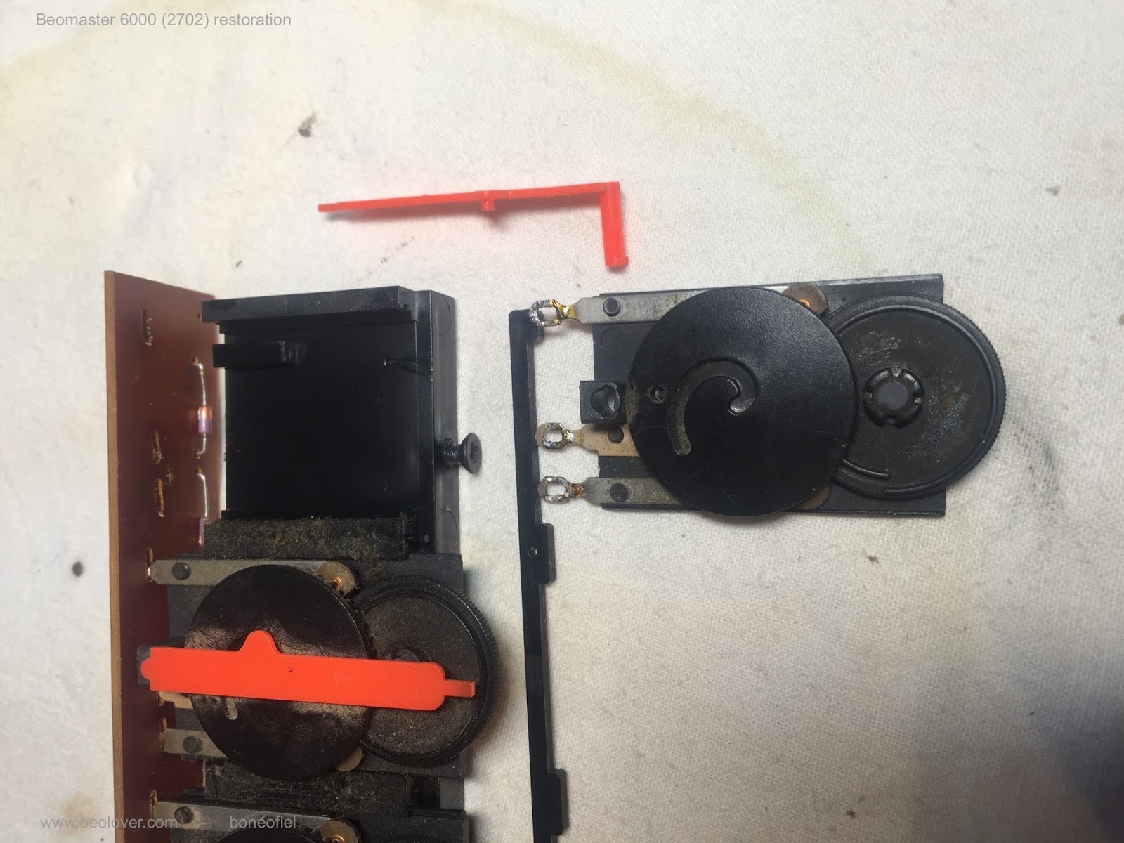
Changing out the original LEDs with modern SMD LEDs is a tedious task and I need to get back in the mode of working them so I will start with the smallest display module first...the channel balance display.
Here is that display with the red lens cover removed. You can see the tiny LED components in the display guide slots. Lining up the replacements in those slots is important.
Here is a further breakdown of the channel balance display. The display guide is now removed to better reveal the original LED components.
Those LED components are quite a challenge for eyes as old as mine. It's a good thing I have plenty of magnifying tools to help me.
Here is a closer look at the original LED component compared to its modern replacement.
For more detail on these displays you can
check out an earlier Beolover Blog of a Beomaster 8000 project I did last year.
I soldered in three of the eleven new LEDs then did a quick test to check the work. So far so good.
After completing the replacement of the other eight LEDs on this lamp module I put it back on the jig for an overnight burn-in test.
The light guide fits perfectly over the new LEDs.
...and here is the lens cover snapped back on. After the burn-in test I will seal this module up better.
Three more display modules to go.