Featured Post

Beolover SyncDrive: DC Platter Motor Replacement for Beogram 4002 and 4004 (Type 551x and 552x)

Late Beogram 4002 and the 4004 (Types 551x and 552x), which have DC platter motors instead of the earlier synchronous AC motors usually suff...

Showing posts with label fiber pen. Show all posts

Saturday, February 3, 2018

Beomaster 6000 (2702) restoration: electronic switch and motor operation board

The Beomaster 6000 quad contains 2 important boards with a whole range of micro switches that are activated by the steel "tongues" on the front panel. They are not the touch-sensitive controls (like on the Bemaster 1900 than came out a little bit later), but pure mechanical contacts with a tiny air-gap of 0,5 mm. Therefore everything needs to be carefully aligned, cleaned and checked if you want to avoid that the user needs to push hard on the key-panel to activate a control. 

So, these 2 boards are recapped, contacts cleaned and all glass bulbs replaced (12V - 30mA plug in type, but with wires pulled out). Again a fiber pen and Deoxit GOLD was used for the contacts.


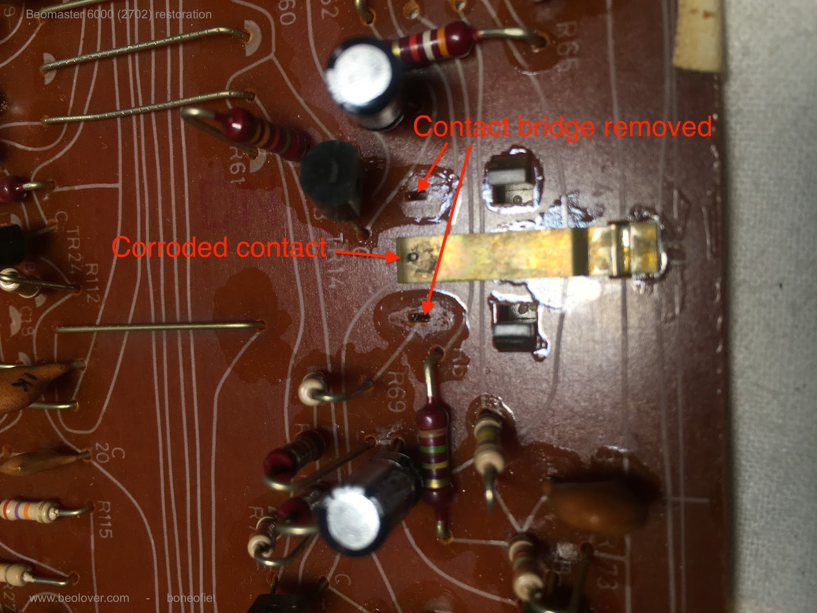
Cleaning the contact bridges


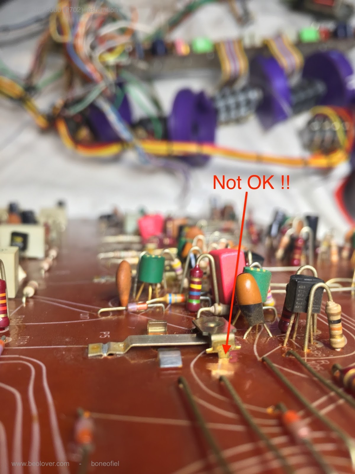
When resoldering the contact bridges it is important that they are fully pressed in the board to get the required 0,5 mm air gap.


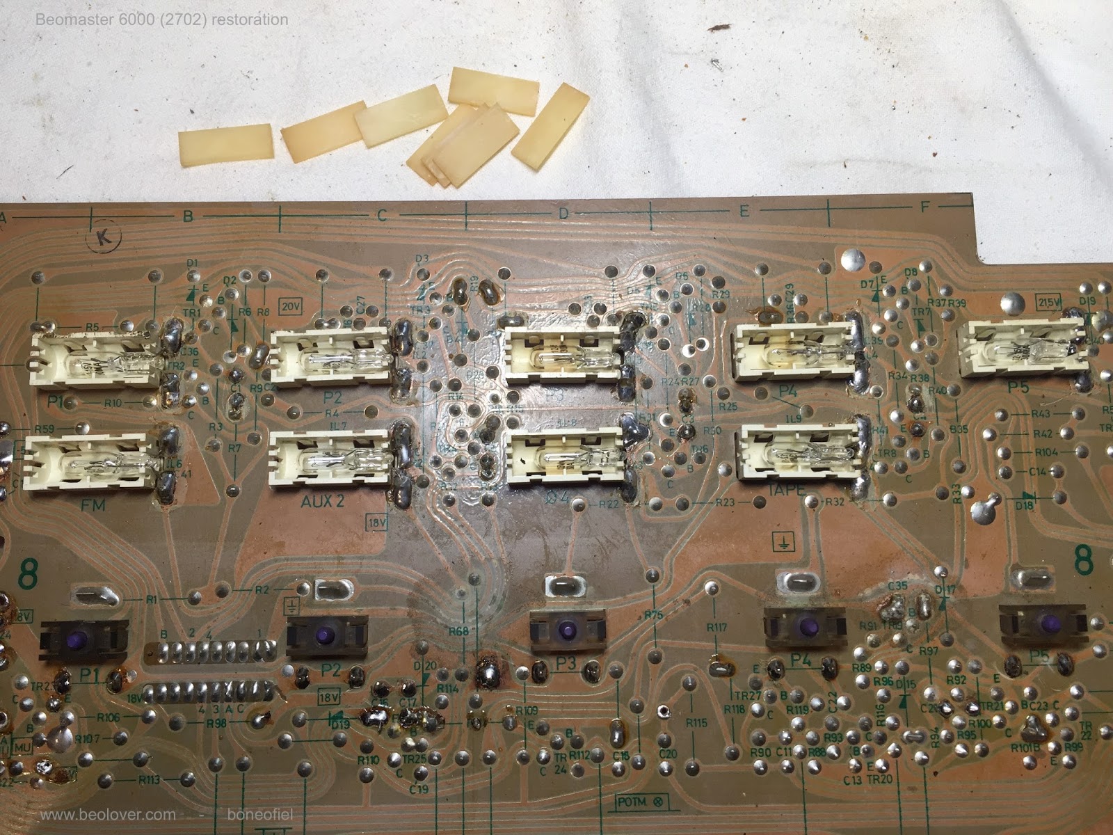
All contacts cleaned !


Time now to turn the board and replace all the glass bulbs


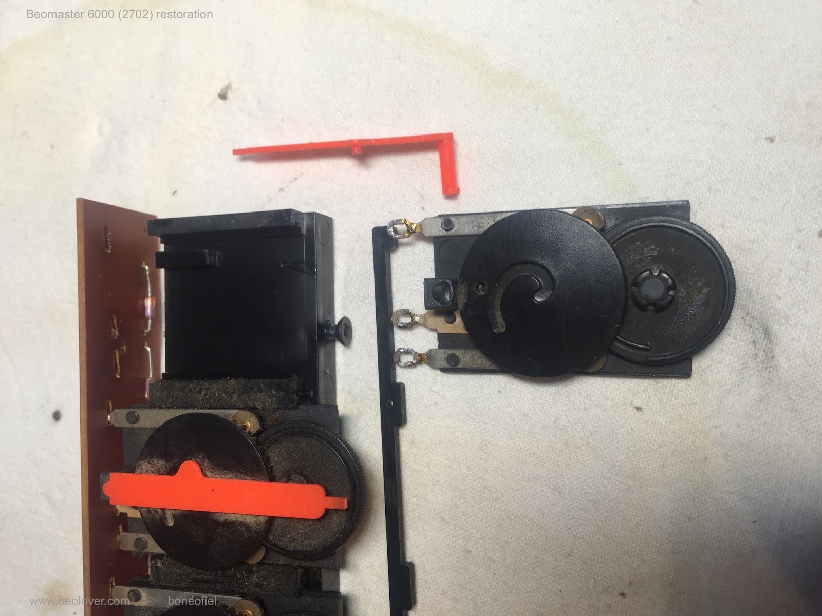
The same thing for the smaller motor operation board. Just cleaning of contacts. No recapping or glass bulb replacement.


Shiny and bright ! Up to the next phase...!

Bemaster 6000 (2702) restoration: the FM preset board

Restoring equipment also requires cleaning. After 40+ years, some units collect dust, a lot of dust as you could see already in one of my first posts "a look inside". The FM preset board was no different. A lot of dust but also corroded trimmer contacts. These trimmers are open types and the board sits just under the front key pannel where you have a lot of "gaps" where dust can penetrate. 


One needs to desolder the 3 trimmer contacts to be able to remove and open them. After desoldering they slide out of the main black plastic holder.


Once you get them out, it is easy to disassemble them. A small retainer clip on the back needs to be removed and then everything "falls apart".


Time to remove the old grease and clean up the carbon and slider contacts. I used a fiber pen and Deoxit GOLD cleaning & coating.


After reassembling I continued with the remaining 4 and cleaned them the same way.


The only thing left now was to solder them back on the board. Important is to make sure they are all pressed completely against the board for perfect alignment before soldering.


Looks good to me !