This post describes the full functional restoration a the Beogram 4004 (Type 5526) that I recently received from a customer in California. My initial assessment of the unit is posted here.
This shows the unit with the aluminum panels removed in as received condition:

As usual with DC motor Beograms, I started with the platter motor. This shows the extracted motor:

I took it apart to get to the bearings:

The bearings are the two small donuts on the black pad. These bearings usually have lost most of the oil stored in the porous Oilite bearing material. This causes the shaft of the motor to run dry with the consequence of RPM fluctuations. This can be remedied by submerging the bearings in motor oil under vacuum. This is shown here where strong bubbling can be seen coming from the two bearings after I pulled a vacuum:

The air bubbles come from the empty pores of the bearing. As the air is being extracted, oil diffuses into the bearings, which restores their ability to lubricate the motor shaft. This process usually takes 2-3 days. The ceasing of the bubbling indicates the end of the process.
While the infusion process was happening, I focused on the other aspects of the restoration. The next step was cleaning and re-lubricating all the moving parts of the arm lowering and carriage transfer mechanisms. This shows the setup in its original condition:

And after removing the components for cleaning:

This show all the parts before I put them into my ultrasonic cleaner:

While the parts were cleaning I removed the final moving part, the damper to arm linkage. It can be seen here from the back of the arms assembly, where it sticks out above the V-shaped notch in the arm that connects to the back of the counterweight assembly:

To get to this linkage the sensor arm needs to be removed. This shows it with the linkage removed:

As usual, the small copper pad that helps the tonearm to move laterally when in up position had come loose. It is only attached with a double sided tape:

I glued it back into place with epoxy and reassembled the sensor arm. Then I put the cleaned parts back in. It is important to put a fresh gasket into the damper:

This ensures a reliable arm lowering experience. The original gaskets are often hardened, which causes inconsistencies in their ability to seal the airflow during the extension of the damper. This can cause sudden arm drops that can be harrowing experiences when there is a cherished $700 cartridge on the arm...;-). This shows all the shiny components back in place:

Next was the replacement of the cracked plastic carriage pulley with a precision machined aluminum reproduction:

The next task on the restoration of the carriage was the replacement of the original incandescent bulb in the tracking sensor with an LED based assembly. This shows the original black bulb housing still in place:

Here one can see it after removal together with its Beolover LED replacement:

The small SMD LED is in the location where the light bulb filament is situated in the original part. This shows it implanted:

There is one more bulb to be replaced on the carriage assembly, the one in the sensor arm. This shows the small compartment pulled out with the original bulb and the LED replacement next to it:

And after replacement of the bulb:

This shows the LED in action. Since it is a special warm light white LED with a sizable red photon emission in its spectrum it is able to light up the B&O logo as beautifully as the original incandescent bulb:

After completing the carriage assembly I focused on the RPM adjustment panel. It contains two light bulbs, which I usually also replace. They often fail, and that does not look very good! But the main reason to update the bulbs with LEDs is the much lower heat emission of LEDs. The hot bulbs have a tendency to cause RPM variations when they heat up the RPM trimmers that are situated right next to them.
This shows the panel after I extracted it:

Removal of the bulb covers reveals the bulbs:

This shows the bulbs removed and the small Beolover LED replacement assemblies:

They solder directly to the terminals that the bulbs connect to:

The bulb covers can be replaced after installation. The LED boards do not interfere with them:

Now it was time to restore the main PCB. The first step is usually to replace the power transistors that are mounted on the solder side of the board. This process is done best with the board still installed since that makes it easy to place the new devices in the proper spot so they line up with the heat sinks and their solder points. This shows one of the original ones, a TIP120 in place:

I replaced it with a stronger TIP102 and a 100nF capacitor on its output:

The capacitor stabilizes the output of the transistor. For some reasons the modern TIP versions tend to have some high frequency oscillations in this circuit design, which can cause issues with the record detection circuitry.
After the power transistor are replaced, the board can be removed for access to the remaining components to be replaced:

I usually replace all the electrolytic capacitors, the power transistors, the RPM relay and RPM trimmers, as well as the sensor transistor and its biasing resistor. This shows the rebuilt board with the extracted components:

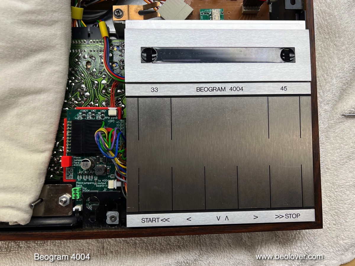
The other board that needs restoration is the output board. It is located under the keypad. I removed the keypad and the board. This shows it in its 'original' condition. Someone replaced the output relay with a not matching relay and did an interesting wiring job to make the necessary connections:

Her you see the beautiful work in all its 'splendor'!...;-):

I removed the relay and installed a proper Beolover replacement assembly that uses a modern encapsulated SMD relay on a custom designed adapter board. I also replaced the electrolytic capacitors and I installed a switch with which one can connect system and signal grounds if there is a hum. This shows the rebuilt board with the removed components:

Here a detail shot of the relay and grounding switch:

At this point it was time to clean out the enclosure from the transport lock bushings mess. The bushings had deteriorated into small fragments that were distributed around the enclosure. I removed the floating chassis and the remaining components. This shows the emptied out enclosure bottom with all the fragments strewn around:

I vacuumed them out:

Now it was time to install new Beolover transport lock bushings. My design comes in two halves, which makes it a snap to install them. This shows them before installation:

Here you can see one of the bushings installed around the transport lock bolt:

I reinstalled the floating chassis with all three bushings restored. Then I installed a new reservoir capacitor. This shows the original one:

They are prone to leaking at this age, so it is a good idea to replace them. I use a modern replacement with a smaller form factor for the same capacitance, and I use a 3D printed adapter to make it fit properly into the original spot:

Now it was time to do some adjustments. First I adjusted the bias of the sensor transistor TR3 to get the prescribed 4V at its collector:

Then I installed the trimmer below deck on the component side of the main PCB and measured the sensor response with the new transitor. I got an impressive 8V amplitude of the sensor signal, which exceeds the spec stated in the manual:

Each dip of the signal corresponds to a black platter rib passing under the sensor. This allows the Beogram to 'see' if there is a record (no signal) or no record (dips like shown above).
The next step was to remedy the strongly bent alignment pins for the aluminum plates. Someone had bent them completely down so they would not touch the aluminum plates. Not very Beolovely, but I can understand the motivation for a regular electronic shop to do it since it can be pretty tedious to adjust their orientation to make the aluminum plates fit properly. Bending them out of the way allows putting the plates in, and as long as the deck is not moved, they stay in place due to gravitation. But of course that is not the way is is supposed to be. This shows one of the pins in its as received bent shape:

Here you can see one of them bent back into the proper position:

With the top plates aligned, I focused on adjusting the arm to platter height, floating chassis level, alignment of the platter with the opening in the aluminum panel that surrounds it. This is usually a routine process, which is a bit tedious since it can take a while, needing multiple iterations until everything is aligned properly.
In this particular case, however, the process went 'beyond routine' when I adjusted the floating chassis. This is done by turning the adjustment nuts that allow tuning the vertical position of the leaf springs that float the chassis. You can see one of the nuts in the picture above. It is located behind the alignment pin. When I turned it it twisted off the bolt. It turned out that someone had epoxied the nuts into place and I did not see that I did not turn the nut on the threads, but rather the bolt itself. The bolt broke off surprisingly easily, which can be explained by the fact that it seems made from aluminum. This shows the broken off bolt with nut:

I made a separate post that shows how I drilled out the stuck part of the bolt. This shows the post with the bolt remnant removed:

Luckily it is possible to replace the drilled out bolt with a standard flat head M4-45mm bolt that can be secured in place with a washer and a nut:

This shows the head of the bolt, how it perfectly fits into the hollow post from the bottom of the enclosure:

It is always a relief when one recovers from a broken bolt event. They can be pretty difficult to deal with.
This shows the replacement bolt in action:

Like it never happened!
Unfortunately, it happened at one of the two other bolts, too: I already had turned it a bit during my initial adjustment attempts, and that was enough to crack the aluminum bolt. So I replaced it with the same method:

I was able to save the third one by heating the bolt with the hot air blower of my soldering station, which softened the epoxy allowing me to remove the bolt and clean the threads while the epoxy was soft.
After all the platter and chassis adjustments were in place, it was time to do the tonearm adjustments. The most important is the tracking weight, which needs a calibration of the counter weight to balance the arm properly. This is done by turning the screw that is in the back of the weight. Since I usually need to ship turntables after the restoration, I need the calibration to be secured in place. Therefore, I replace the circlip that holds the screw in place with a M3 nut that allows tightening down the screw in the proper spot. This shows the original clip still in place:

And here the nut installed:

I usually try to calibrate the counter weight to get the proper weight at the 1.2g setting of the weight adjustment wheel:

This wheel is notorious for being off across some of its adjustment range. It essentially torques a spring when it is turned adding or subtracting force to the arm. Generally, it is best to use a digital scale and simply turn the wheel until the proper weight is dialed in, regardless of what the scale on the wheel shows.
The next step was the adjustment of the arm lowering limit, which is an important failsafe to protect the needle from damage should the arm ever drop on an empty platter in the case of a circuit malfunction. The arm limit should be about 1 mm above the lower sections on the ribs (which are located at the three drop positions for LPs, 10" records and 7" singles):

The final adjustment was the tracking feedback to ensure that the carriage follows the needle properly as it advances towards the center of the record:

On the way to a first test spin of this deck I needed to remedy the unbeolovely output cable mess, where a RCA adapter was essentially hotwire to the original DIN5 cable after cutting off the plug:

I removed the spliced in RCA cable and installed a new all-metal DIN5 plug with gold plated terminals, essentially restoring the factory setup:

Beogolden!
My customer decided to let me install the Beolover Commander remote control system, which allows controlling all functions of the deck without touching the keypad. This is a great way to extend the lifespan of the fragile coating that is giving the keypad its distinctive looks. The Commander also adds autorepeat functionality and gives the deck an improved fast forward scan feature that automatically stops when the forward/backward buttons are let go.
The installation of the Commander is an easy 'plug and play' process that does not require any soldering (check out the video that is posted under the above link). The first step is taking out the keypad for installation of the special breakout adapter that connects the Commander's power supply to the power rails of the Beogram:

The next step is the installation of the Commander board. It piggybacks on top of the main PCB using one of the threaded holes that the PCB bolts screw into. Here you can see the installed Commander and its connection via the white wire harness to the adapted below the keypad:

Now the grey keypad plug can be plugged back into the breakout adapter:

And the main black keypad plug goes into the socket on the Commander board:

The final installation step is bolting the autorepeat LED into the space beneath the RPM adjustment panel. It uses the same screw that holds the keypad assembly in place:

The IR remote receiver needs to be fed in between the plinth and the metal enclosure so it can poke out below the plinth when the Beogram is completely assembled:

Now the RPM panel can be replaced and that is about it:
Here a view of the completed installation:

Now it was finally time to do the RPM stability measurement. I do it with all restored motors to check if everything is in good shape. This measurement is done with the BeoloverRPM device, which can log the RPM in 10s intervals for long periods of time. Ideal to catch those elusive random RPM variations:

This is the curve I measured after about 24 hrs:

This curve is pretty stable, but shows some slow drift. Probably a consequence of the top bearing being slightly differently oriented after re-assembly of the motor. These motors are pretty finicky when it comes to friction phenomena. After running for a few decades the bearings actually end up polished where the belt pulls the motor shaft towards the platter center. After the restoration process this position can be slightly off and some motors need a few dozen hours to settle with the new bearing alignment. The measured RPM drift is so slow that it could not be detected by the human ear. The important aspect of a satisfying motor restoration is the absence of sudden large RPM spikes like they typically occur with dry bearings.
Now it was finally time to give this beautiful Beogram a first test spin! I selected one of my favorite Bob James records, "Touchdown", which was produced in 1978. Of course this album was cleaned ultrasonically on a CleanerVinyl ProXL setup before play! This shows the Beogram together with this lovely album:

Beolovely! I will now play this Beogram for a couple weeks and if nothing else comes up, it will soon be time to send it back to its owner in California!


