This post describes the restoration of an AC-motor Beogram 4002 (Type 5503), which I recently received from a customer in Oklahoma. My initial assessment of this unit was posted earlier here.
This shows the unit as received with the aluminum panels removed:
When I received the unit it came with a few loose parts, one of them the spring of the shut off (SO) switch. This shows the switch without the spring:
Luckily, I was able to reinsert it and the switch still worked properly:
the first step of the restoration focused as usual on cleaning and re-lubricating the moving parts of the carriage assembly:
I removed all the parts partaking in arm lowering and carriage translation:
This shows the components before I cleaned them in an ultrasonic cleaner:
With the carriage up, it was the perfect moment to rebuild the carriage PCB. This shows it in its original condition:
This unit had an incandescent bulb in the carriage position sensor. This shows the bulb after removal of its housing:
I replaced it with a white LED and a 3.3k resistor (the bulb runs on 24V):
This shows the LED implanted, as well as the new capacitor and solenoid resistor that also need replacing on this board:
In the meantime the parts had finished their cleaning process in the ultrasonic:
As usual, the solenoid arm extension was cracked around the rivet:
I replaced it with a 3D printed part:
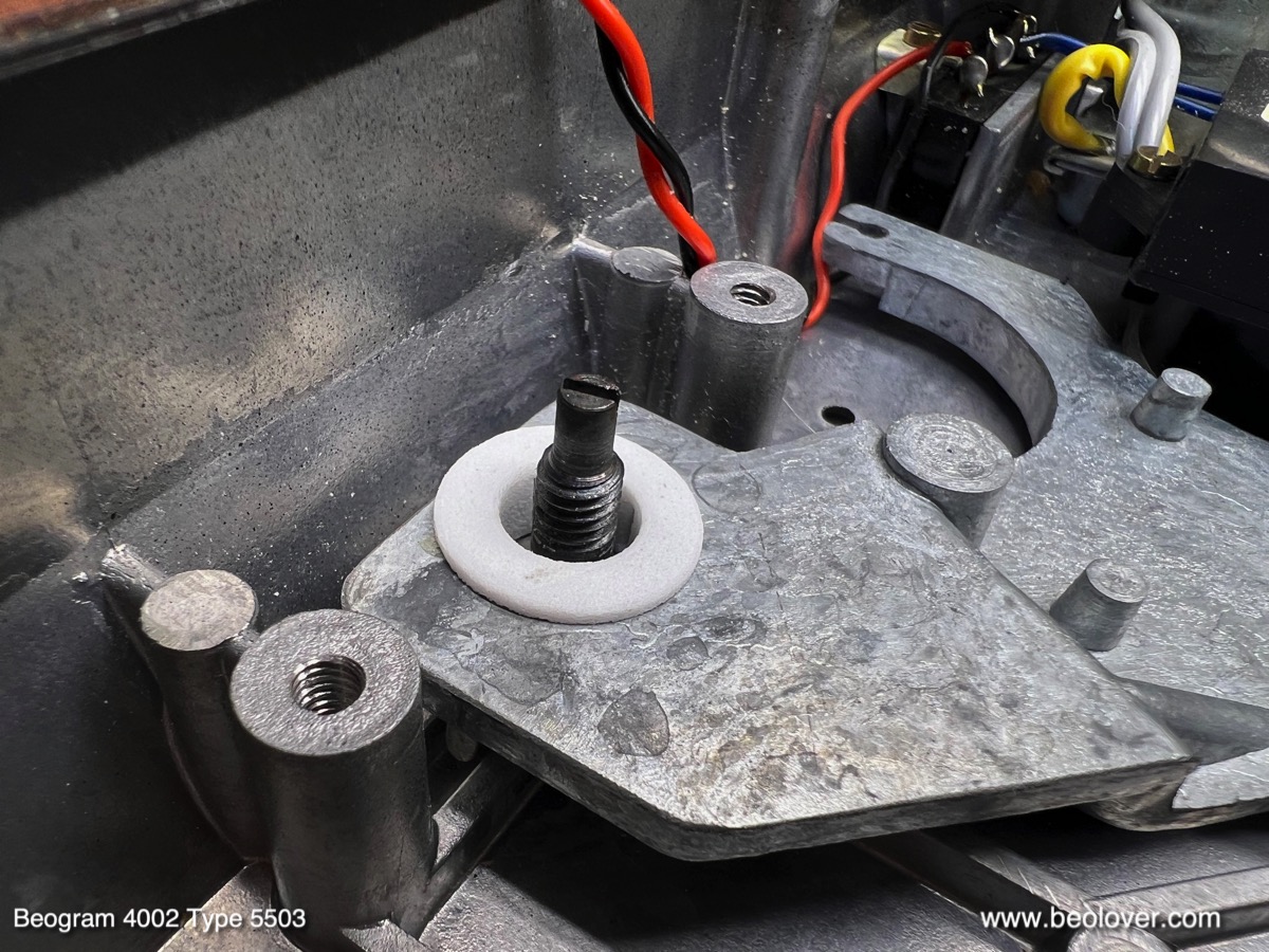
An important item is the replacement of the damper gasket. This shows a new rubber washer installed:
This ensures that the arm lowering process is consistent. The original washers are often hardened or deformed, which can cause intermittent arm lowering with much less damping than usual. A hair raising experience when you have a $600 cartridge on the arm!...;-)
After re-installing all cleaned parts, I focused on the damper-to-tonearm linkage, which has its pivot point located on the sensor arm assembly. The linkage can be seen from the back of the arms. It is the small lever that pokes out from the V-shaped notch in the arm that is attached to the back of the tonearm counterweight:
For lubricating the pivot point the sensor arm needs to be unbolted from the carriage:

After cleaning and lubricating I put everything back together and re-installed the sensor arm assembly. As usual the small copper plate that helps the arm to laterally move when it is up was loose due to degraded double sided tape. I cleaned it and epoxied it back into place:
The final step was re-aligning the arms. They need to be parallel and orthogonal to the carriage rods:
As the final 'carriage task' I replaced the cracking-prone carriage pulley with an aluminum replica:
This shows the carriage back together:
The next step was restoring the AC platter motor. It is shown here below the big reservoir and motor capacitor cans:
I extracted the motor
and took it apart by drilling out the rivets that hold it together:
I immersed the enclosure halves in motor oil and pulled a vacuum. As usual strong bubbling started as the air was extracted from the motor bearings and various other porous components:
While the oil infusion process was proceeding I focused on restoring the remaining parts of this Beogram. I removed the output board

and replaced the output relay and its time constant defining capacitor:
I also installed a switch with which one can connect system and signal grounds in case there is a hum. This is often a good way to get rid of hum when connecting a Beogram to an amplifier with RCA inputs.
Then I removed all other components from the enclosure
so I could vacuum out all the fragments from the completely decayed transport lock bushings. This photo shows the fragments around a lock that was removed:
I vacuumed everything out:
While the enclosure was empty, it was a good moment to replace the power transistors of the AC motor push-pull stage. I replaced them with stronger TIP41/42 types:
I also replaced the solenoid transistor with a new TIP41C, a high voltage version of the original TIP41:
My hope is that the higher voltage version will withstand the stresses imposed by the solenoid better.
Then it was time to put the floating chassis back in with new transport lock bushings. This shows the Beolover replacement bushings. They are made from two halves that can be installed easily by simply using one half in from the bottom and the other from the top:
This shows one bushing installed on the extracted chassis::

and after putting the chassis back into the enclosure:
Next came the restoration of the main PCB:
I usually replace all electrolytic capacitors, all power transistors, the RPM trimmers and the high gain transistor of the sensor arm circuit:
There are usually also two capacitors soldered to the copper side of the PCB. This shows the original tantalum types:
I replaced them with modern capacitors:
Then I focused on replacing the reservoir and motor capacitors. This shows the installed new capacitors neatly organized by a 3D printed fixture:
This shows the backside of the assembly as well as the re-assembled AC motor
There were still three light bulbs that needed to be replaced: First I focused on the two in the RPM adjustment panel. This shows the extracted panel from the back:
I removed the bulb covers:
As usual the 33 RPM cover showed traces of heat deformation. Clearly a result of mainly playing 33 RPM records...
I removed the bulbs and installed the Beolover LED assemblies. They solder directly to the bulb solder terminals:
They do not interfere with the bulb covers. This shows the covers re-installed:
The last bulb to be replaced was in the sensor arm compartment. This shows the pulled out compartment with the original bulb installed and the Beolover LED assembly next to it:
This shows the LED board installed and the extracted bulb:
This Beogram had the usual cracked plinth guidance washers:
I replaced them with 3D printed nylon replicas:
The black one goes up front so it cannot be seen through the crack between enclosure and plinth. This shows one of the white ones installed on the sides of the plinth:
Now it was time to do some measurements. First I checked the motor AC signal. This shows the ~57 Hz signal that is to be expected for 45 RPM,
and this the ~42 Hz signal for 33 RPM:
Next was the adjustment of the tracking feedback:
Unfortunately, at this point I had to realize that this deck was not tracking! A visual inspection of the circuit board that connects the tracking sensor assembly to the main circuit revealed a crack that severed the photo resistor in the sensor from the main circuit:
I soldered two bridges in,
which restored the tracking function. After adjusting the tracking feedback I set the bias for the sensor arm transistor (TR9). I usually install a 5MOhm trimmer replacing the fixed 1MOhm bias resistor (R33) so I can precisely dial in the 4V at the collector that the manual specifies:
After moving the adjusted trimmer 'below deck' I installed the platter and measured the sensor response at the collector of TR9. I saw a healthy >7V amplitude which is an A grade!:
All good in the important record detection department!
Next I adjusted the platter arm distance and leveled the platter relative to the arm movement. Then the floating chassis was adjusted to yield a platter that is flush with the surrounding aluminum panels.
Once these adjustments were completed I calibrated the tracking weight of the tone arm. First I replaced the circlip of the counterweight adjustment screw
With a M3 nut:
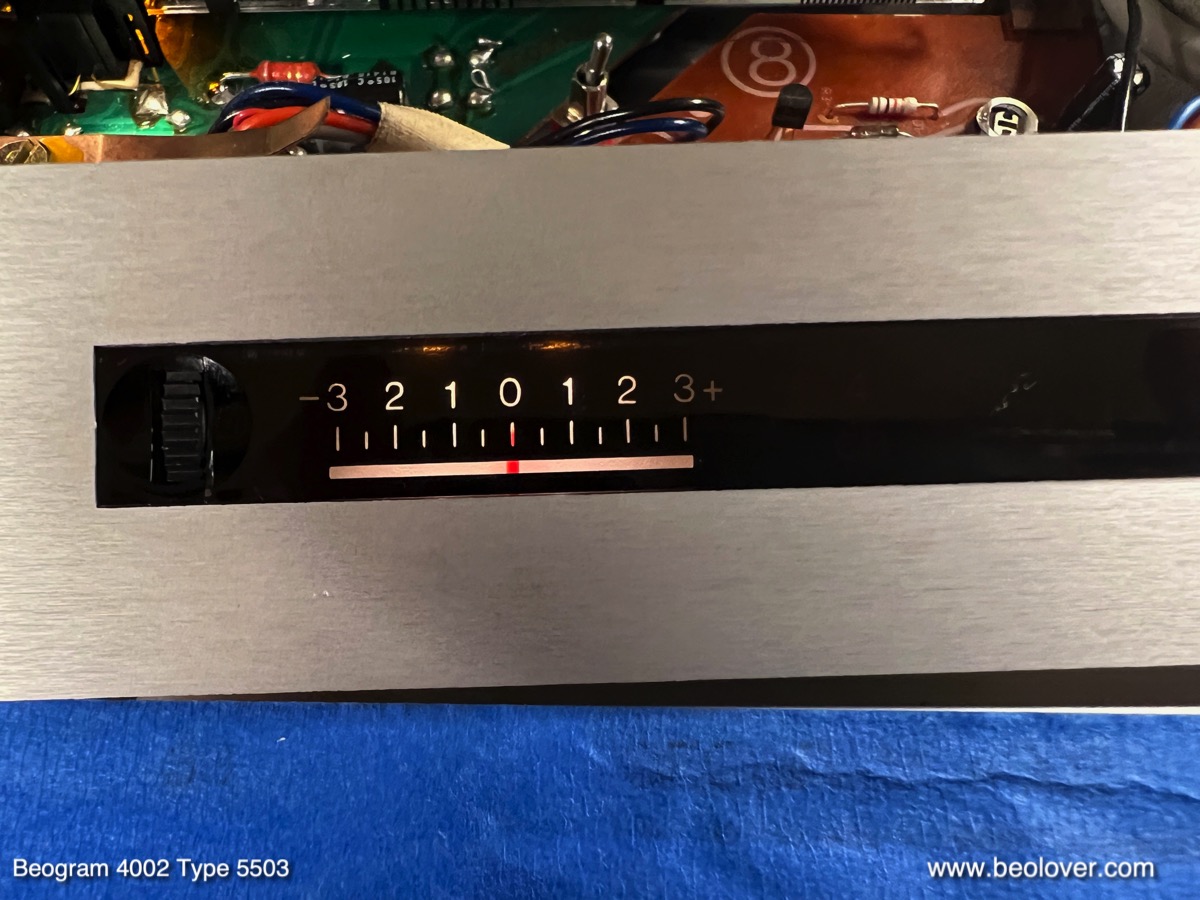
Then I calibrated the tracking weight dial to be reasonably accurate around 1.2g, which is the typical weight at which B&O cartridges track best:
Then it was time to adjust the arm lowering limit:
This is an important adjustment that acts as a safeguard for the case of a malfunctioning record detection circuit, which might permit the arm to be lowered onto the platter without a record present.
At this point I realized that this Beogram 4002 5503 had the typical wavy background in the 33 RPM adjustment scale:
I removed the RPM panel once more and opened it up. This shows the white background of the 33 RPM scale.
The heat load from the bulb did not only deform the bulb cover as seen earlier, but also the plastic foil that serves as background. I replaced both 33 and 45 backgrounds with cut to size portions of 3M white electrical tape:
After reassembly the background was pristinely uniform:
Then I finally replaced the original corroded DIN 5 plug

with a modern all-metal type fitted with gold plated terminals:
The next step was running a 24 hrs RPM test with the
BeoloverRPM device, which allows logging the RPM in 10s steps. This is the curve I measured:
An excellent result. Though as usual, since the AC motor Beograms only very rarely have issues with RPM stability. A consequence of the classic synchronous motor based design.
Beolovely! And now it was finally time to give this Beogram a first spin! I selected one of my favorite Eddie Henderson records,
"Comin' Through" that he recorded in 1977 (Capitol Records ST 11671). Of course this vintage record was ultrasonically cleaned using a CleanerVinyl ProXL setup to restore it to its original glory! A perfect match for this beautiful Beogram 4002:
It played beautifully with the rare MMC6000 cartridge that came with it.
The next step will be installing the
Beolover Commander remote control system to protect the still very nice keypad of this Beogram, as well as an internal
Beolover RIAA preamp that will replace the output board and will allow connecting this Beogram to any high-level amplifier inputs like AUX or DVD. Perfect for using this classic deck with a modern amp that does not have a dedicated phono input anymore.