Featured Post

Beolover SyncDrive: DC Platter Motor Replacement for Beogram 4002 and 4004 (Type 551x and 552x)

Late Beogram 4002 and the 4004 (Types 551x and 552x), which have DC platter motors instead of the earlier synchronous AC motors usually suff...

Friday, September 8, 2023

Beogram 4002 (5503): Complete Functional Restoration

This post describes the restoration of an AC-motor Beogram 4002 (Type 5503), which I recently received from a customer in Oklahoma. My initial assessment of this unit was posted earlier here.

This shows the unit as received with the aluminum panels removed:

When I received the unit it came with a few loose parts, one of them the spring of the shut off (SO) switch. This shows the switch without the spring:
Luckily, I was able to reinsert it and the switch still worked properly:
the first step of the restoration focused as usual on cleaning and re-lubricating the moving parts of the carriage assembly: 
I removed all the parts partaking in arm lowering and carriage translation:
This shows the components before I cleaned them in an ultrasonic cleaner:
With the carriage up, it was the perfect moment to rebuild the carriage PCB. This shows it in its original condition:
This unit had an incandescent bulb in the carriage position sensor. This shows the bulb after removal of its housing:
I replaced it with a white LED and a 3.3k resistor (the bulb runs on 24V):
This shows the LED implanted, as well as the new capacitor and solenoid resistor that also need replacing on this board:
In the meantime the parts had finished their cleaning process in the ultrasonic:
As usual, the solenoid arm extension was cracked around the rivet:
I replaced it with a 3D printed part:
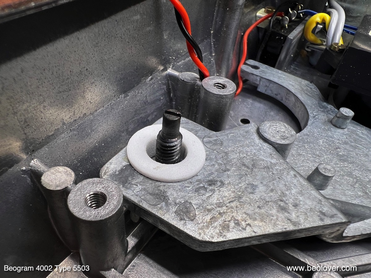
An important item is the replacement of the damper gasket. This shows a new rubber washer installed:
This ensures that the arm lowering process is consistent. The original washers are often hardened or deformed, which can cause intermittent arm lowering with much less damping than usual. A hair raising experience when you have a $600 cartridge on the arm!...;-)
After re-installing all cleaned parts, I focused on the damper-to-tonearm linkage, which has its pivot point located on the sensor arm assembly. The linkage can be seen from the back of the arms. It is the small lever that pokes out from the V-shaped notch in the arm that is attached to the back of the tonearm counterweight:
For lubricating the pivot point the sensor arm needs to be unbolted from the carriage:
After cleaning and lubricating I put everything back together and re-installed the sensor arm assembly. As usual the small copper plate that helps the arm to laterally move when it is up was loose due to degraded double sided tape. I cleaned it and epoxied it back into place:
The final step was re-aligning the arms. They need to be parallel and orthogonal to the carriage rods:
As the final 'carriage task' I replaced the cracking-prone carriage pulley with an aluminum replica:
This shows the carriage back together:
The next step was restoring the AC platter motor. It is shown here below the big reservoir and motor capacitor cans:
I extracted the motor
and took it apart by drilling out the rivets that hold it together:
I immersed the enclosure halves in motor oil and pulled a vacuum. As usual strong bubbling started as the air was extracted from the motor bearings and various other porous components:
While the oil infusion process was proceeding I focused on restoring the remaining parts of this Beogram. I removed the output board 
and replaced the output relay and its time constant defining capacitor:
I also installed a switch with which one can connect system and signal grounds in case there is a hum. This is often a good way to get rid of hum when connecting a Beogram to an amplifier with RCA inputs.

Then I removed all other components from the enclosure
so I could vacuum out all the fragments from the completely decayed transport lock bushings. This photo shows the fragments around a lock that was removed:
I vacuumed everything out:
While the enclosure was empty, it was a good moment to replace the power transistors of the AC motor push-pull stage. I replaced them with stronger TIP41/42 types:
I also replaced the solenoid transistor with a new TIP41C, a high voltage version of the original TIP41:
My hope is that the higher voltage version will withstand the stresses imposed by the solenoid better.
Then it was time to put the floating chassis back in with new transport lock bushings. This shows the Beolover replacement bushings. They are made from two halves that can be installed easily by simply using one half in from the bottom and the other from the top:
This shows one bushing installed on the extracted chassis::
and after putting the chassis back into the enclosure:
Next came the restoration of the main PCB:
I usually replace all electrolytic capacitors, all power transistors, the RPM trimmers and the high gain transistor of the sensor arm circuit:
There are usually also two capacitors soldered to the copper side of the PCB. This shows the original tantalum types:
I replaced them with modern capacitors:
Then I focused on replacing the reservoir and motor capacitors. This shows the installed new capacitors neatly organized by a 3D printed fixture:
This shows the backside of the assembly as well as the re-assembled AC motor
There were still three light bulbs that needed to be replaced: First I focused on the two in the RPM adjustment panel. This shows the extracted panel from the back:
I removed the bulb covers:
As usual the 33 RPM cover showed traces of heat deformation. Clearly a result of mainly playing 33 RPM records...
I removed the bulbs and installed the Beolover LED assemblies. They solder directly to the bulb solder terminals:
They do not interfere with the bulb covers. This shows the covers re-installed:
The last bulb to be replaced was in the sensor arm compartment. This shows the pulled out compartment with the original bulb installed and the Beolover LED assembly next to it:
This shows the LED board installed and the extracted bulb:
This Beogram had the usual cracked plinth guidance washers:
I replaced them with 3D printed nylon replicas:
The black one goes up front so it cannot be seen through the crack between enclosure and plinth. This shows one of the white ones installed on the sides of the plinth:
Now it was time to do some measurements. First I checked the motor AC signal. This shows the ~57 Hz signal that is to be expected for 45 RPM,
and this the ~42 Hz signal for 33 RPM:
Next was the adjustment of the tracking feedback:
Unfortunately, at this point I had to realize that this deck was not tracking! A visual inspection of the circuit board that connects the tracking sensor assembly to the main circuit revealed a crack that severed the photo resistor in the sensor from the main circuit:
I soldered two bridges in,
which restored the tracking function. After adjusting the tracking feedback I set the bias for the sensor arm transistor (TR9). I usually install a 5MOhm trimmer replacing the fixed 1MOhm bias resistor (R33) so I can precisely dial in the 4V at the collector that the manual specifies:
After moving the adjusted trimmer 'below deck' I installed the platter and measured the sensor response at the collector of TR9. I saw a healthy >7V amplitude which is an A grade!:
All good in the important record detection department!

Next I adjusted the platter arm distance and leveled the platter relative to the arm movement. Then the floating chassis was adjusted to yield a platter that is flush with the surrounding aluminum panels.

Once these adjustments were completed I calibrated the tracking weight of the tone arm. First I replaced the circlip of the counterweight adjustment screw
With a M3 nut:
Then I calibrated the tracking weight dial to be reasonably accurate around 1.2g, which is the typical weight at which B&O cartridges track best:
Then it was time to adjust the arm lowering limit:
This is an important adjustment that acts as a safeguard for the case of a malfunctioning record detection circuit, which might permit the arm to be lowered onto the platter without a record present.

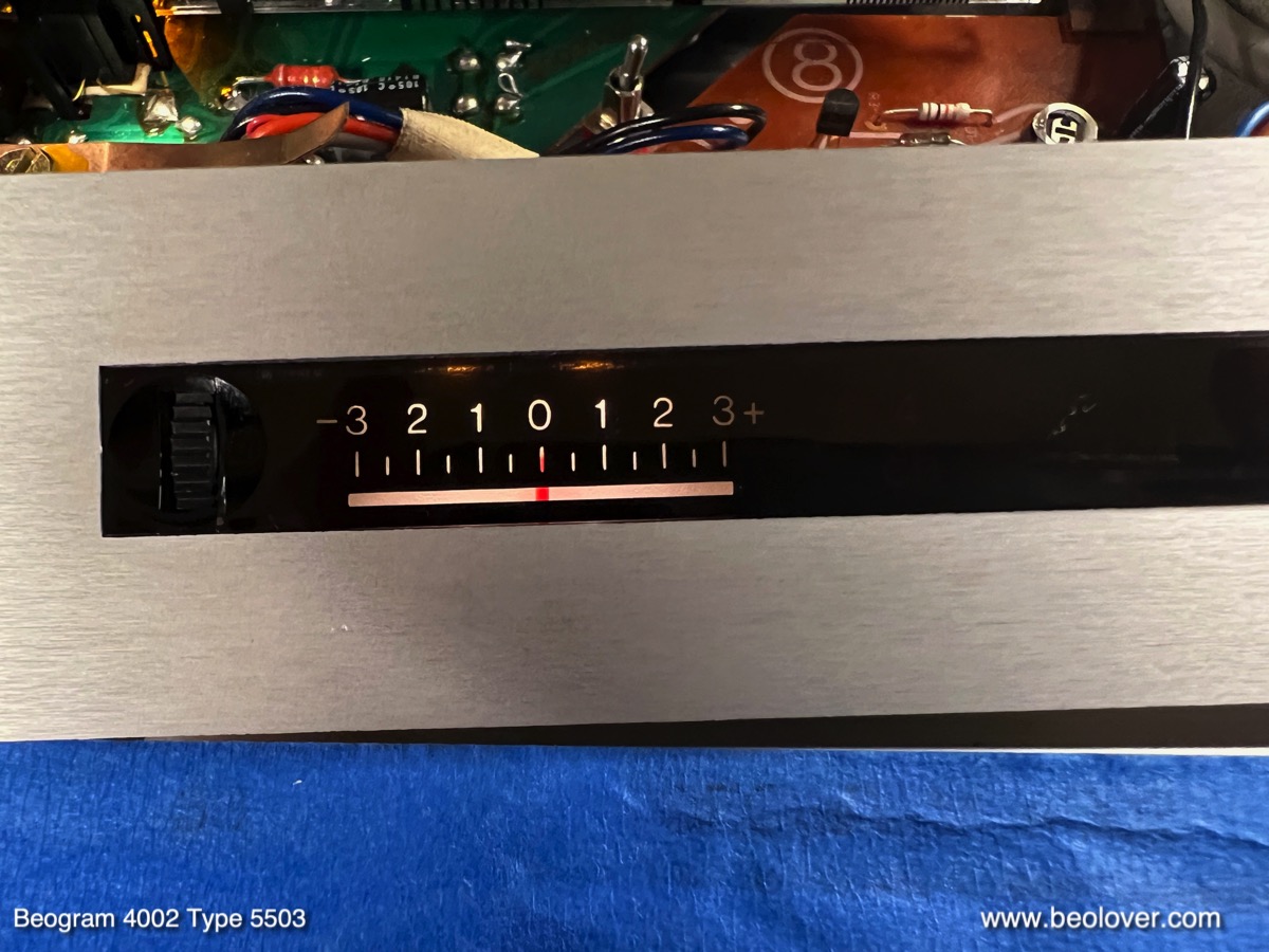
At this point I realized that this Beogram 4002 5503 had the typical wavy background in the 33 RPM adjustment scale:
I removed the RPM panel once more and opened it up. This shows the white background of the 33 RPM scale. 
The heat load from the bulb did not only deform the bulb cover as seen earlier, but also the plastic foil that serves as background. I replaced both 33 and 45 backgrounds with cut to size portions of 3M white electrical tape:
After reassembly the background was pristinely uniform:
Then I finally replaced the original corroded DIN 5 plug
with a modern all-metal type fitted with gold plated terminals:
The next step was running a 24 hrs RPM test with the BeoloverRPM device, which allows logging the RPM in 10s steps. This is the curve I measured:

An excellent result. Though as usual, since the AC motor Beograms only very rarely have issues with RPM stability. A consequence of the classic synchronous motor based design.
Beolovely! And now it was finally time to give this Beogram a first spin! I selected one of my favorite Eddie Henderson records, "Comin' Through" that he recorded in 1977 (Capitol Records ST 11671). Of course this vintage record was ultrasonically cleaned using a CleanerVinyl ProXL setup to restore it to its original glory! A perfect match for this beautiful Beogram 4002:
It played beautifully with the rare MMC6000 cartridge that came with it.
The next step will be installing the Beolover Commander remote control system to protect the still very nice keypad of this Beogram, as well as an internal Beolover RIAA preamp that will replace the output board and will allow connecting this Beogram to any high-level amplifier inputs like AUX or DVD. Perfect for using this classic deck with a modern amp that does not have a dedicated phono input anymore.


Beomaster 5500 Type 2333: New Beomaster Restoration Project From St. Louis

Most of my Bang & Olufsen restoration projects are on analog components from the seventies and early eighties.  However, I do own fully restored Beosystem 5000 and 5500 components which are from the mid to late eighties.  Those systems always include a CD player of course and continued the fully integrated system remote control that B&O started in the early eighties.

This project is a restoration of a Beomaster 5500 from an original owner.
It is an analog audio component that has a digital control system for operating it (Master Control Panel MCP5500).  

Here is the initial assessment of its condition.


It is a little dusty but that isn't a problem as I will be cleaning it as I do the restoration work.

The shiny aluminum top trim piece is pretty marked up.  That is due to the other Beosystem 5500 components stacked on top.  B&O designed these components to be stacked so it isn't a surprise to see the tops showing signs of wear like this.

The Beoparts store sells replacement aluminum trim to restore the cabinet if someone wants to make it new looking again :-).

Here is the back view of the cabinet.


A feature that I really love about the B&O cabinet design on these is how easy it is to open it up for servicing.

Two screws are loosened (not removed...and lost).  That allows two locking brackets to be raised up and held in place by tightening the screws again.


The unlocked cabinet top then slides back a little and lifted off.

Here is the Beomaster 5500 with the cabinet top removed.


The five highlighted screws are removed next to allow the AM/FM Stereo Tuner board to lift up into service position.

Some of the screws were loose so I suspected this Beomaster had been in for some service at some point in its history.


Flipping the unit around I could see that the audio muting relay has been replaced already.
That is a component I would have replaced if it was still original.


The same type of relay was used for the power supply rail voltages.  They get disconnected when the Beomaster 5500 is in Standby mode.

That relay is still original so I will be replacing that one.

Next, I removed the translucent, plastic air duct the helps cool the output amplifier components.


Everything looks good so far. 

Now to see if the Beomaster 5500 can be turned on and switch through its operation modes.

To do that I will use my own MCP5500 (Master Control Panel).
Unlike the Beomaster 5000, the Beomaster 5500 does not have a control panel built into it.
There are a couple of push buttons on either side of the front panel to turn the Beomaster on and off...plus some really minimal source switching.  You have to use the MCP to really operate this receiver.

Plugging the Beomaster 5500 in, it goes into Standby mode, which is what it is supposed to do.


I exercised the operation of the Beomaster with the MCP and could hear the relays engage when I went out of Standby mode.


It appears that all of the selectable functions work so I am ready to move forward and start the restoration.

From what I have seen so far I will replace all of the old electrolytic capacitors with new capacitors.
I will replace the power on relay.
I will also re-flow solder joints on the boards.  That will guard against any unseen breaks in the electrical paths.
The Beomaster has a small, lithium battery for its built in memory to remember user settings.
I will replace that battery.
The thermal compound on the output amplifier heatsink looks like it is still soft (not dried out).
So I probably will leave that as it is unless I see the amplifier getting too hot during testing.

This Beomaster 5500 cabinet is missing its rubber cabinet feet.  That is pretty common and expected.
I will replace those feet with a set that Beoparts reproduces.  Typically all of the audio components in these B&O systems (5000, 5500, 6500, 7000) have missing or broken cabinet feet.

Once I get the restoration work complete on this receiver I will be able to test it using my various Beosystem 5500 components and the MCP5500.


Thursday, September 7, 2023

Beogram 4002 (5503): When Disaster Strikes! - Replacement of the Solenoid Switch and Restoration of a Melted Solenoid

Oh well! I recently received a Beogram 4002 (Type 5503) from a customer in Arizona with the indication that 'it does not lower the arm anymore'. I had restored the unit only in Dec. 2022, so this was a bit early for my taste to see it again!

After I removed the aluminum panels it became immediately clear why the arm would not lower again!:

The solenoid had completely melted down! I measured its resistance and it was about 1.2 Ohms. Normally it should have about 9 Ohms. Why this happened also became clear quickly. My solenoid arm extension part did not hold up. It cracked in a very similar way like the original arm extensions:
Because of this weakened arm link the solenoid switch did not get activated anymore and so the solenoid ran at full power even after the arm had been lowered. At some point the insulation of the coil wiring burned off, short circuiting the coil and that was the end of the arm lowering function. 
I extracted the solenoid
and took it apart:
Then I made a new coil. Luckily I recently learned how to do that:
This shows the new solenoid installed in the original bracket:
After I implanted the solenoid I had to realize that it would not activate at full power. This turned my attention to the solenoid switch. I found it to have a too high resistance when closed. And that caused the solenoid to be underpowered. Maybe the switch-terminals also suffered during the solenoid burnout. But it also did not click properly when activating it manually, so there was something wrong with its mechanics, too.
Since these switches are not made anymore, I had to figure out a 'modern replacement'. Immediately, I thought about the end switches used in 3D printers. They have a suitably small form factor, but they usually are only rated for switching DC currents up to an amp or so. Not enough for handling the typical 3-4 Amp current in the Beogram solenoid when it is activating. 
After a bit of thought I decided to try using a power transistor for the 'heavy lifting', and the switch only for activating the transistor. This approach promised reducing the mechanically switched current by about 2 magnitudes since the current gain of such transistors is typically in the 100x range. In other words the switched current promised to only be in the sub-100mA range. 
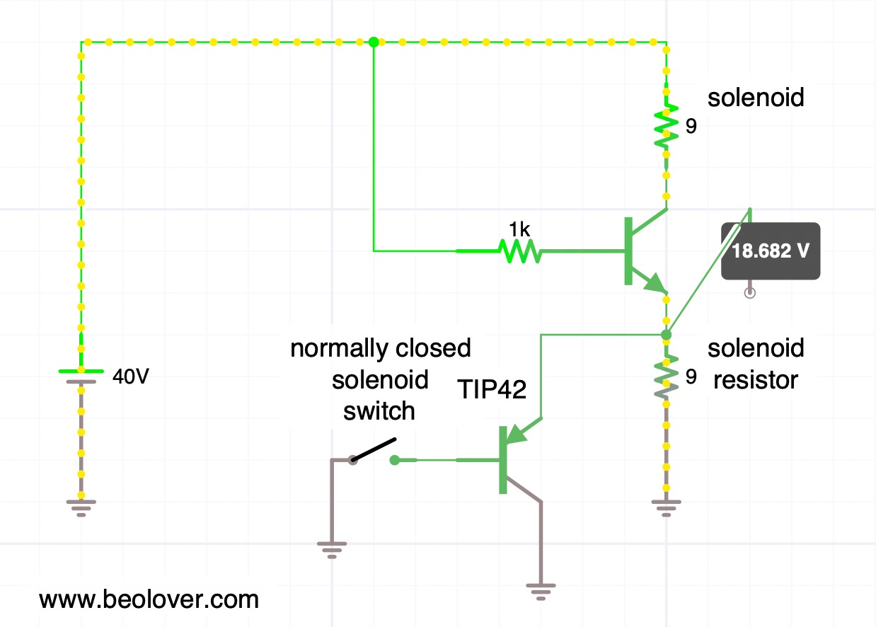
This is the simple circuit that I implemented using a end switch connected as a normally closed switch, so the TIP42 pnp transistor would be on when the solenoid is initially fired up to sink the solenoid directly into ground. This is the situation shown here (yellow beads show the main current flow):
You see that the simulation shows a voltage of about 0.7V at the emitter of the solenoid transistor. This means that the solenoid sees almost 40V driving it with about 4.3 amps based on its approximate 9 Ohms resistance.
After the solenoid activates and pushes its plunger out the solenoid switch gets hit and the TIP42 turns off, sending the current solely though the solenoid resistor. This causes the voltage across the solenoid to be dramatically lowered and with that the current gets reduced:

This situation is maintained during the play of a record when the arm is down.
This shows this concept put into practice on the solenoid switch PCB that I extracted to be able to work on it:
I found the best switch position by trial and error, and then drilled a hole into the circuit board so I could anchor it with a 2mm bolt in place. The TIP42C is bolted in via one of the two mounting screws of the PCB. The way it is connected still allows the board to be be shifted up and down to fine tune the switch position. This is important to make sure the arm hits the switch in a way that it really switches.
The last task was the re-design of my solenoid arm extension. I got rid of the nut and instead used a self-tapping 2mm screw that would put only minimal stress on the plastic. I added a liberal amount of epoxy in the bolt hole and the compartment that receives the end of the metal arm to keep things from separating. This shows the result:
Let's hope this holds up better!
Here you can see the arm in concert with the switch. First with the solenoid off:

And now with the solenoid activated:
Once the solenoid demonstrated to actuate properly, I measured the voltage across it during the activation process. In this measurement the trace corresponds to the signal measured at the collector of the solenoid transistor (0TR4).
But first I measured a reference signal that I was able to obtain conveniently from another 5503 that I have on the bench currently:
Before activation of the solenoid, the voltage at the collector is essentially the same as the power rail, i.e. ~40V. This means the solenoid has 0V across it. Once the solenoid transistor activates, the voltage across the solenoid increases to about 40V and then, after about 10ms, the solenoid arm hits the switch, and the solenoid gets disconnected from ground, and the current flows through the solenoid resistor instead. This results in a strong voltage reduction across the solenoid and it has now only about 8-10V applied to it. This real-life voltage is less compared to the simulation above. I think it comes from the fact that in the simulation I drive the solenoid transistor with an arbitrary 1k resistor connected to 40V, while in the real circuit a series of transistors (TR14/15/16) drives it with a different current.
What really counts is: Does the TIP42 replacement result in a similar behavior as with the original switch? Happily it does as is evident from this trace that I measured on the implemented circuit:
This trace is hardly distinguishable from the standard circuit behavior and so we can conclude that this may be a good fix for broken solenoid switches!
All good again in the arm lowering department of this Beogram 4002! Beolove is sometimes a bit painful, but only steady improvement leads to perfection. And that is what the Beolover aims to achieve!


Friday, September 1, 2023

Beogram 4002 (5513): Repair of a Broken Sensor Arm Photocell with Three SMD Photodiodes

I recently restored a Beogram 4002 (Type 5513), which had a broken photocell in the sensor arm. One of the electrodes had come off from the photocell:

Here a picture of the removed photocell:
These photocells are not available anymore, and previously a solution involving using a modern phototransistor and a small circuit modification to adapt it onto the Beogram record detection circuitry had been developed.

When I encountered the above, I first wanted to replicate the phototransistor solution, but then I remembered that a photovoltaic cell (aka 'solar cell') is in its simplest form just a pn-diode. Such diodes can actively generate a current when exposed to light if a load is connected. The photocell in the sensor arm is basically such a diode. It generates a light induced AC current (as the platter ribs pass through underneath it) that is fed via a capacitor (to keep DC components from background light out) into the base of a transistor (TR3 in the 5513 circuit) that amplifies this current, which is ultimately used to drive a transistor that disables the arm lowering mechanism.

So the thought occurred to me that one could potentially use a photodiode and simply replace the photocell without further circuit modification. Phototransistors do not generate significant currents by themselves due to their symmetrical npn or pnp junction configurations, and therefore they need added circuitry in this case.

I ordered a few photodiodes for visible light detection that had a suitable form factor for this project. Indeed, most of them showed various voltages when exposed to light. I ended up using a PIN (p-type/insulator/n-type junction) silicon cell in a 0805 SMD package. I soldered two 32 gauge wires to it for testing: 
It yielded 0.45V into the 10 MOhm of my multimeter when exposed to my fairly strong bench LED lights:
I installed it using the original insulator tubes:
And I got a decent response at the collector of TR3 when I spun the platter under it and pushed the extracted sensor compartment a couple mm towards the platter. But the signal was still too small and had an inverted look:
I concluded that a single diode did not have enough current capability under the given light situation for driving TR3 properly, so I decided to replace it with three units connected in parallel for my next test. I also reversed the polarity:
I installed the assembly. This time I did not use the insulator tubes, but instead supported the leads by a small piece of suitably thick cardboard. I fixated the leads to it with a dab of epoxy to hold everything in the correct position:
And I measured a nice 5.72V amplitude at the collector at TR3 with the sensor compartment properly inserted into the arm!:
I also tested it with and without record on the platter and the arm did not stop or lower on the empty platter, as it should. All good again in the sensor arm department! This Beogram is ready to be sent back to its owner in California!