Featured Post

Beolover SyncDrive: DC Platter Motor Replacement for Beogram 4002 and 4004 (Type 551x and 552x)

Late Beogram 4002 and the 4004 (Types 551x and 552x), which have DC platter motors instead of the earlier synchronous AC motors usually suff...

Tuesday, April 14, 2015

Beomaster 8000: Shipping Damage Repair II

Today, had a look into the soft FM 'store' button. I took out the control panel and removed the PCB. This is what I found:


Some of the tabs that hold the PCB for the buttons were broken off. The previous owner had removed this PCB at some point and did not understand that it can be slid to the left after lifting the end of the PCB above the blocking plastic protrusion. So he broke the tabs off and re-attached them with the solder iron that he used as a welding tool when he put the board back in...very crafty! Unfortunately, this method does not yield very good bonds, which resulted in structural failure during the shipping accident. The tab that stabilized the PCB beneath the FM store button was missing, resulting in sagging of the PCB when the button is pressed. That resulted in a soft feel when the button was used.

I fixed the issue with a few dabs of heat gun glue essentially replacing the reattached tabs for a more lasting bond. The great thing about this type of glue is that it can be removed with a bit of mechanical force. That way one can get in there again if needed. Here is a picture:

Time to put the Beomaster back together for some testing.

Monday, April 13, 2015

Beomaster 8000: Shipping Damage Repair

A sad moment in Beolover's life! A Beomaster 8000 that I recently restored was damaged during return shipping to its owner. FedEx must have dropped the box off the truck. This Beomaster was even shipped in its original box, but this was apparently not good enough. Double boxing is really worth the effort! So far, I only had shipping issues with single boxed units.

Anyway, upon opening it up and plugging it in, the display looked like this:


The Beomaster also occasionally turned off by itself, when touching the processor PCB...all this suggested some broken tracks on this PCB. And indeed, a close inspection of the board revealed several broken traces around one of the slots for the shield in the PCB...I bridged the affected traces:

And everything started working again:

It is interesting to understand the phenomenon cause by the broken traces. All strobed display digits had a very low intensity. At first I was a bit confused how all of them could be affected at the same time, while the non-strobed segments ran at full intensity. But all cleared up once I realized that the ground connection of both 74247 7-segment decoders had a high resistance. This floated them, and hence they were not able to sink current anymore, and with that the LEDs were all dim.

So far so good. Unfortunately, there is some more trouble: The buttons of the control panel feel unusually tight. They still work, but there is definitely something wrong...


Friday, April 10, 2015

Beomaster 8000: The Mystery of Swapped Tape 1 and 2 In- and Outputs and a Broken Damper Arm (Sad Story)

A Beomaster 8000 that I recently restored showed a strange phenomenon when I hooked it up to my Beogram 8000 and Beocord 9000 for in-situ testing: When I pressed start on the Beocord, the Beomaster came on with the Tape 1 input selected as it should due to the Beolink connection between the two. However, there was no sound from the tape (and no recording either as I found out shortly after). However, I was able to hear the playback signal very faintly when I cranked the Beomaster up to full volume. This indicated that there was something fundamentally wrong with the Tape inputs. The plot thickened when I hooked my iPad up to the Tape 1 input and only got sound out of the receiver when selecting Tape 2. Then I connected it to the Tape 2 input, and, you guessed it, I needed to select Tape 1 to be able to listen to it.
It appeared that the inputs were swapped...very strange!

The Beomaster went back to the bench, and I opened it up. Then I traced the signals to plug P3 on PCB3 (preamp). And indeed both in- and output leads were swapped on this plug, effectively connecting Tape 1 to the Tape 2 connections on ICs 202/102, while Tape 2 was connected to IC4.

I removed the terminals from the plug housing and replaced them in the correct order. I made a schematic for future reference:


After this I thought everything was fine, and I tested the inputs. And indeed, now I plugged in the source to Tape 1, and it played when selecting Tape 1 as input. The same for Tape 2. Great! (I thought!). But then I played with the 'input level presets' (potentiometers accessible from the outside of the Beomaster that allow to attenuate the inputs if a signal source is too strong). This yielded another surprise: Now the Tape 2 presets affected the Tape 1 input, and the Tape 1 presets affected the Tape 2 input...very strange! But of course much better than the original situation where I was not able to use my Beocord properly. Still strange!

After scratching my head a bit, I remembered that some Beomasters come with a different connector box, where the tape RCA connectors are connected to the Tape 1 input instead of Tape 2. At that point it dawned on me what probably happened to this Beomaster 8000 of unknown ebay provenance:

The previous owner swapped the original input box that had the RCAs on Tape 1 with an input box  from an other Beomaster that has the RCAs on Tape 2, and it seems that these two configurations have Tape 1 and Tape 2 swapped on P3 that connects to the circuit board.

Here is a pic that compares the two boxes and shows their P3 terminal arrangement:


Note the different arrangement of the Tape in and out RCAs on top and the input level presets labeled below. Tape 1 and 2 are swapped. At this point it escapes me why B&O would have changed the P3 pinout...there is really no reason, they could just have connected the RCAs to Tape 1, relabeled the box and been done with it.

It is interesting to note that all Beomaster 8000 circuit diagrams that I so far have seen show the "standard configuration", but there is a significant percentage of Beomasters that have the "RCA on Tape 1 configuration"...

Anyway, this Beomaster is working now as it should (as long as one remembers which input level presets to use) and my Beocord works happily with it.

Some bad news: While putting the left side of the Beomaster back together after rearranging the inputs, a 'petit malheur' happened: When I bolted the control panel lid back onto place, and closed it a loud crack occurred, and then the lid was undamped. first I thought the linkage broke, as it has before, but no, a more spectacular problem arose:

The damper arm cracked into two pieces:

This picture shows the arm fragment still attached to the linkage with the broken off part:

Here is a shot of the two cracked parts assembled with the damper:
And the broken arm separately:
I guess it is time to fire up a 3D printer...;-). Small parts like these are an interesting printing challenge to get the proper fit and stability. Stuff for another blog entry.


Sunday, April 5, 2015

Beomaster 8000: Display Repair (II) - Reassembly and Final Test

This is the second part of a Beomaster 8000 display restoration post. The 24hrs test of the installed SMD LEDs passed uneventfully. So I put the displays back together. I used the 'glue gun method' I developed recently to secure the display covers back in place. I really like this method, since it seems to make a strong lasting bond, while still leaving a way to cleanly opening the displays up again should there ever be a problem again down the road. I usually try to stay away from the use of glue etc...due to the often irreversible character of the outcomes. But in this case there are not many options. But the unique properties of the polyurethane glues used in glue guns makes a clean reversal possible. My tests showed that the glue can be fully removed without leaving residues if necessary.

After putting them back together I tested them again in my fixture:

Seems all went well! So I installed them back on the PCB:

Here a detail shot of the input display. One of the two glue strips is visible on the side:

I installed the board again in my Beomaster 8000 and applied my standard intensity adjustment procedure:

Another Beomaster 8000 display restored to full glory! This is Beolove!


Saturday, April 4, 2015

Beomaster 8000: Display Repair (I) - Installation of SMD LEDs and Test

Last week I was sent a Beomaster 8000 display board for rebuilding the displays with surface mount LEDs. I installed the display into one of my Beomasters and had a look:

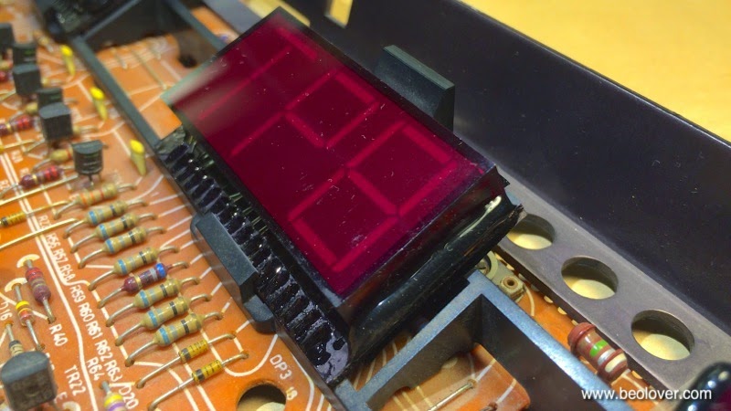
Many segments were dead. A clear case for a rebuild. As usual the balance display was still good. So far I have to find a broken balance display yet. Their boards look differently, i.e. they seem to have come from a different manufacturer. I set out to rebuild the display with SMD LEDs. Here are a few pictures of the process. Display board removed:
Displays liberated. It is best to take the top three out at once. Otherwise it is easy to damage the plastic alignment fixture:
Removed from the plastic fixture:
Opened up:
This shows the frequency display board after removing the original LEDs:
SMD LEDs lined up for population of the board:
After installing all LEDs. Now I will run them for 24hrs in my test fixture to make sure everything is stable:


Friday, April 3, 2015

Beogram 4002 (5513): Replacing the DIN 5 Cable with a Cable Featuring RCA Plugs

The Beogram 4002(5513) that I am currently rebuilding will be used together with a McIntosh Preamp, i.e. the DIN5 connector that is standard on Bang & Olufsen equipment is inconvenient. The best solution with regards to shielding and lowest-possible EMI is to install a new cable with RCA connectors right at the source of the signal inside the turntable. Adapters are never a perfect solution.

Aiming for excellent sound quality, we decided to go with an solder-ready open ended RCA cable supplied by Sounds Heavenly in the UK. This cable features individually shielded left and right cables using a twisted-pair arrangement between signal and return path. At any rate, it looks very 'audiophile'...;-). I made a short video discussing the original DIN 5 arrangement, the installation of the RCA cables, and the differences between the 4002, 4004, DIN and RCA grounding and shielding schemes:


Here are a couple pictures of the installation. This one shows the new cables installed into the original plug of the DIN 5 cable:

And this shows the cable entry to the Beogram and the RCA plugs:


Thursday, April 2, 2015

Beogram 4002 (5513): Re-Attaching Keypad Segments

The 'beautification stage' of my current Beogram 4002 (5513) restoration continues: The final touch was to re-attach two delaminated keypad sections. Here is a picture of the issue:

I put a bit of superglue gel under the pads and clamped them down with vise grips:

One needs to be careful to not put too much glue there, since any excess can potentially reach the top of the pads, whose delicate paint surface can easily get irreversibly damaged by the glue. So my recommendation is to start with very little glue and see if it holds. If not put a bit more. Patience always pays off with such projects...;-).

This one worked out well the first time. All good now in keypad land: