Featured Post

Beolover SyncDrive: DC Platter Motor Replacement for Beogram 4002 and 4004 (Type 551x and 552x)

Late Beogram 4002 and the 4004 (Types 551x and 552x), which have DC platter motors instead of the earlier synchronous AC motors usually suff...

Friday, February 22, 2019

Beogram 4004 (5526): Tracking Sensor LED, Non-Working Carriage Switches, Final Adjustments and Test Drive with Eddie Henderson

The restoration of the Beogram 4004 (5526) that is on my bench is coming to an end. This post describes the final tasks of the project. After replacing the sensor arm bulb with an LED, I tested the carriage functionality and it behaved like the end switch and the turn off switch both did not work. It turned out that the wires that connect the switches to the main PCB had broken off from their solder points (white and grey wires):


I reconnected them (the grey wire needed to be extended a bit since it was pretty short after taking some insulation off for re-soldering):


After this repair everything seemed to work in terms of carriage motion.

The owner decided to also let me replace the bulb in the tracking sensor compartment with a LED assembly. I recommended this since this is also an essential light source, whose failure would disable the Beogram.

This shows the original tracking sensor light source in place:
I removed the bulb housing, which reveals the aperture that activates the sensor in the lower half of the assembly:
This shows the original bulb and the LED replacement in comparison:
The LED is in the same location like the filament of the bulb. This shows the LED assembly in place:
The blue trimmer allows fine tuning of the tracking sensor response, which makes it easier to adjust the system to spec. I also replaced the standard often rusty sheet metal screw that secures the aperture assembly in place with a M2 stainless socket head screw and a matching nut. This makes the initial coarse adjustment of the aperture position much easier.

Now it was time to adjust the platter height and the floating chassis horizontality. Then I moved on to the tonearm adjustments. An important item is adjusting the arm lowering limit. It needs to be set in a way that the needle 'misses' the ribs on the platter at the setdown points as an additional safeguard against needle damage should the record detection mechanism ever fail and the arm gets lowered onto the naked platter. This shows the adjustment result:
Then I moved on to the tracking weight. The first step is usually replacing the flimsy retaining clip on the counterweight screw with a M3 nut. This allows tightening the counter weight position down, which preserves the calibration over time and during shipping. This shows the original setup:
And with M3 nut:
Then it was time to calibrate the measured weight with the adjustment scale. I usually do it at 1.2g, since that is the weight at which most B&O cartridges track best. The weight scale on the adjustment wheel is notoriously imprecise, i.e. it is always best to confirm the weight with a digital gauge:
After this I adjusted the tracking feedback:
And then I tried to play a record...and all I got was a very loud hum from the speakers! Unbeolovely, entirely!
Hum usually means a broken connection in the grounding system between amplifier and turntable. It turned out that the shield connection in the DIN plug was disconnected:
Since the original DIN plugs cannot be opened up without destroying them, I needed to install a new plug:
The gold coated pins are a nice improvement in the signal path over the original corroded pins. This quenched the hum and the deck started sounding properly.
So it was time to listen to a nice record and enjoy this lovely 4004! I picked a recent addition to my collection, "Comin' Through" by Eddie Henderson. Of course this vinyl was cleaned with a CleanerVinyl Easy6 before I played it! Henderson recorded this album in 1977, and there are a few great funky tunes on it. My favorite is "Movin' On" on the first side. 
Beolovely! I will play this Beogram 4004 for a few more days and then it will be time for the return trip to its owner!


Thursday, February 21, 2019

Beogram 4004 (5526): Replacement of Sensor Arm Bulb with a LED

After restoring the record detection circuit and the PCBs it was decided that the sensor arm light bulb should also be replaced with a LED to ensure operability of the deck down the road. These old light bulb like to fail, especially during shipping, i.e. it is a good idea to replace the bulbs with LEDs when restoring a Beogram. This shows the original light bulb in the sensor compartment together with the replacement flexPCB-based LED assembly:
I removed the bulb and inserted the LED board, which folds snugly into the compartment:
This shows the LED in action:
The LED is a warm-white type, i.e. there are enough red photons to ensure a properly colored B&O logo.
Whenever the light source in the sensor arm is replaced, the sensor response needs to be checked. The signal strength is highly dependent on the location of the light source in the compartment. The signal at the collector of the signal amplifying transistor TR3 needs to be close to 6V or better. This shows the measurement I made after the installation:
This Beogram record detection circuit is now operating better than spec (7.9V amplitude), i.e. we can confidently press the START button. 


Sunday, February 17, 2019

Beomaster 1900 Type 2904: Capacitor Replacement Part 2 and Slider Control Repair

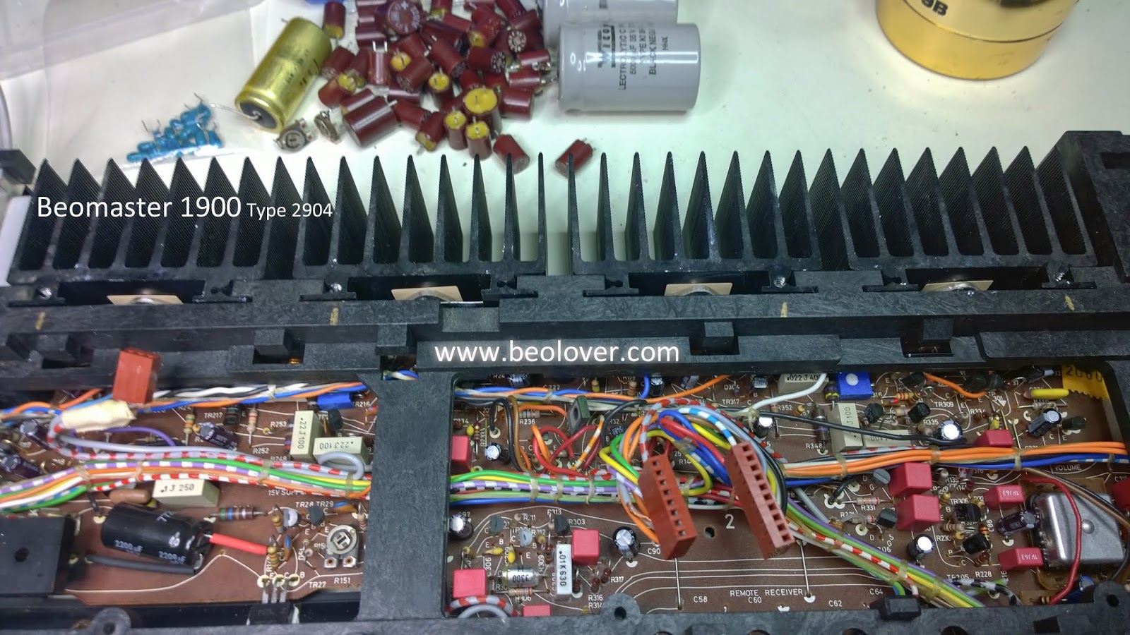
All of the electrolytic and tantalum capacitor replacement tasks are complete now on this Beomaster 1900 project.

The last board was the tone control and FM tuning board.

There are are only eight capacitors to replace on that board. Here are two before pictures.


...and here are the after pictures. Very straight forward.


The larger task on this board is the repair of the three slider controls (bass, treble and balance).
It is very common for these controls to fail on the Beomaster 1900. The failure is mechanical and involves the plastic slide that holds the left and right channel contacts for the respective control.


A small plastic tab that holds the metal contact in place breaks and the contact becomes free to move around. This results in faulty or no sound in one or both channels.

I noticed at least one loose contact when I did my initial assessment of the Beomaster. To be sure of the condition of all the sliders they must be disassembled and checked.

It is a good idea to label the slide controls as they are removed from the board.


Two small, metal tabs on the end of the control must be bent straight so the metal clamp/holder can release and allow the contact slide mechanism to be removed.

Here are all three sliders disassembled. I found three with broken contact mounting tabs.


The repair for this problem is best made using a repair kit from Martin Olsen. Martin makes a number of  accurate replacement kits for various vintage Bang & Olufsen components that he sells on his Beoparts website.

In this case the kit consists of three replacement (plastic) slider control parts plus some useful instructions.


I cleaned the metal contacts and slider areas with Deoxit (cleaner and fader lube). Then I reassembled the slider controls.


Next up are the lamp replacement tasks.

Thursday, February 14, 2019

Beomaster 1900 Type 2904: New idle current trimmers and output transistor thermal insulators

I started to work on replacing the electrolytic capacitors on the last board, the tone control and FM tuning control board. Unfortunately I ran out of my favorite 2.2uF WIMA capacitors. There is a Mouser distribution center close to me however so the parts will arrive tomorrow.

In the meantime I will go ahead and change out the left and right channel 250Ω trimmer resistors that are used to adjust the output amplifier no-load current. Now is a good time to change them.

Here are pictures of the trimmer replacements.


Along with that change I cleaned off the old, dry thermal insulation paste on the four output transistors that are mounted on heatsinks in the back of the Beomaster. I like replacing that with new Sil-Pad thermal insulators.


Here are the heatsinks reinstalled.


Wednesday, February 13, 2019

Beomaster 1900 Type 2904: Capacitors replacement Part 1

Most of the electrolytic and tantalum capacitors have been replaced on this Beomaster 1900 now. That replacement was long over due and badly needed. Over eighty percent of the capacitors I replaced measured out of tolerance or completely dead.

I will start with a couple of pictures showing the recapped main board.


Being packaged into such a low profile cabinet the Beomaster 1900 circuitry is mostly on one big board (labeled module 2 in the service manual).  There are a few other small boards with a few electrolytic and tantalum capacitors but the majority of the task is the large module 2 board.

The capacitor replacement was pretty standard....desoldering, measuring and replacing one capacitor at a time. It takes extra time to measure the old and new capacitors but I like to know that information on each restoration.

The Beomaster 1900 did have a couple of capacitor replacement tasks that took some extra work.

The reservoir capacitors 0C7 and 0C8 don't have a bracket to hold them and utilize the original capacitor's large, flat terminals to connect up all of the ground and power lines to them.


To make that task a little easier I mounted a terminal between the two grounded posts of the new reservoir capacitors to secure them together. I also added multi-tab terminals to the two posts for the power wires.


This Beomaster 1900 has a modification not shown in my service manual in the left and right volume related circuitry. This board wasn't in the previous Beomaster 1900 project I did.

This picture shows the small mod board attached to the main board.


There is one lone tantalum capacitor in the FM tuner (metal) box that I replaced.


The volume control board has two small tantalum capacitors that I also replaced.


The last couple of pictures show the replacement of the +15VDC power supply capacitor 2C92.


That just leaves the capacitors on the tone control and FM tuning control boards. I will show that on the next blog post for this project.

Saturday, February 9, 2019

Beogram 4004 Type 5526: RIAA preamp board hiccup and fix on Beogram 4004 Turntable #1 from Dallas

In the last post of the Beogram 4004 Turntable #1 from Dallas I installed Beolover's custom RIAA preamplifier board he designed for the Beogram 4002 turntable.

I left off in that post with the Beogram 4004 ready to check that the original functionality of the modified output board still worked. In other words, the normal mode where the phono cable is connected to an amplifier that provides the RIAA preamp.

That test worked perfectly so it was on to try out the new RIAA preamp mode of the Beogram 4004.
I switched the two connectors from the original module 8 connectors P8 and P9 to the two connectors on the Beolover RIAA preamp board.

Now I would be able to connect the Beogram phono cable to an amplifier's auxiliary, tape or CD source input connectors and listen to the Beogram.

I was surprised when I tried that and the Beogram 4004 would not respond to any of the control panel buttons.

Thinking about it for a few moments I realized that while the Beogram output board on the Beogram 4002 and 4004 have the same P8 and P9 connectors, the BG4004 has an extra connector and circuitry for its remote control capability with a Beomaster 2400.

Here is a diagram of the Beogram 4004 output board and its additional remote control circuit.


The part of the diagram below the dashed red line is the phono output (with muting relay) that does not involve the remote control. The Beolover RIAA preamp board uses those two connectors to perform its function. Switching the P8 and P9 connectors between the original module 8 output board and the RIAA preamp board allows switching between the original, no RIAA output and the RIAA amplified output from the Beogram.

With the additional remote control support circuitry in the Beogram 4004 some of the P8 inputs are needed in the remote control circuit and work with the Beogram control panel via the additional P10 connector on the output board.


When I move the P8 and P9 connectors from the original output board to the RIAA preamp board the original output board loses its 30V, 21V and system ground wiring. Those are not only necessary for the remote control circuit but also for the control panel switches in the Beogram 4004.

That is the reason the Beogram 4004 acts dead when the P8 and P9 are configured for RIAA preamp mode.

The fix turned out to be simple. When the P8 connector is moved from the original board to the Beolover RIAA preamp I must have jumper wires keep those key pins (30V, 21V and system ground) between the boards connected.

Here is a diagram of the output board with the RIAA preamp board after the jumpers were added.


I retested the Beogram 4004 with the Beolover RIAA preamp board again by connecting it to the Tape 1 input DIN jack on my Beomaster 6000.


It works awesome!

This is a great mod for a Beogram 4002/4004 turntable. With this modification all of the record play bases are covered. In a vintage audio system where the amplifiers were designed with specific phono inputs you can use the Beogram with the output connectors in their original position. When you need to connect to a modern amplifier that has no phono record play support you can set the Beogram to use the RIAA board.

I will definitely want to do this same mod on one of my own Beogram 4002 or 4004 turntables.
Time to put this cabinet back together and get the Beogram ready for delivery to its owner.