Featured Post

Beolover SyncDrive: DC Platter Motor Replacement for Beogram 4002 and 4004 (Type 551x and 552x)

Late Beogram 4002 and the 4004 (Types 551x and 552x), which have DC platter motors instead of the earlier synchronous AC motors usually suff...

Sunday, December 10, 2017

Beogram 4000: Replacement of a Cracked Cartridge Mount with a 3D Printed Assembly

Like so many Beogram 4000s, the one I am working on right now had a cracked MMC cartridge mount. In the 4000 this part was made from a more brittle plastic than in the later 4002s, and it seems this material is not aging well. This is how this issue manifests itself:
The first step of this repair procedure is to take the arm out that the original part can be extracted. For this the screw in the back needs to be removed, and then the arm can be pulled out:
after pulling it forward a bit the part that holds the excenter down can be removed, revealing the excenter and the spring that pushes it down:
Pulling the arm further releases a spring that holds the wiring in place:
The the arm comes off and one can see the board where the wires to the cartridge mount are soldered on:
The next step was to unsolder the wires. Two of them are soldered to the bottom side of the small board:
These can be unsoldered using a mirror and carefully operating the soldering iron to get underneath from the side. After unsoldering the wires it was time to 'cook' the arm for a while to soften the glue that holds the MMC mount in place:
This one needed to be heated for an hour or so until I was able to finally push the cartridge out with a metal rod that fits into the square arm profile:
Unfortunately, this 'pushing out procedure' often results in damaged wires since there is no way to keep them out of the way while pushing the mount out from the back. In this case I had to replace two of them...this shows the 3D printed replacement part with the transferred wires soldered on:
The next step is to install the mount together with the original bottom part:
I usually glue the parts back into the arm with white wood glue (Alene's, but any other will do, too). When doing this, care needs to be taken when the mount assembly is pushed into the arm that it is inserted precisely at a depth that allows to mount the cartridge snugly. This is best done by putting a cartridge on and then pushing the mount in with the cartridge:
After letting the glue harden for 24 hrs, the cartridge can be removed:
Now the arm can be installed again:
And bolted to the carriage:
Allright! On to replacing the sensor arm light bulb with an LED assembly...


Saturday, December 9, 2017

Beogram 4004: Happy End!

I recently restored the main PCB, the DC motor and the RPM trimmer panel of a Beogram 4004 located in Denmark. I also tested the MMC20EN cartridge. Then I sent the parts back to Denmark. After being stuck in customs for a few days they were installed back in the 4004. Testing yielded a nicely working deck and a couple happy customers. They sent me this lovely picture with the instruction to feature it on the blog:

Beohappiness! And an awesome record on the platter! 

Thursday, December 7, 2017

Beogram 4000: Restoration of the AC Motor and Replacement of the Reservoir and Motor Capacitors

After restoring the PCBs of the Beogram 4000 that is currently on my bench it was time to look after the reservoir and motor capacitors, and the AC motor itself. This shows the capacitor and motor section of the deck in original condition: 
I started removing the old cans and found that the big ones had started leaking:
So it was definitely high time to get this done. This shows the capacitor bay after removing them:
I also removed the motor (this was a good moment since its leads were already unsoldered from the capacitors):
The motor is held together by threaded rivets. If one wants to open the motor to re-lubricate the bearings, these rivets need to be drilled out. This is how the motor looked like after returning from my drill press:
I opened it up
A very simple yet elegant construction! Made in Switzerland...those were the days...;-).
This is a close up of the rotor with everything that sticks on the shaft:
I immersed the two halves of the motor housing with the bearings in oil (it seems there is no obvious way to get the bearings out without doing major damage) and pulled a vacuum to draw oil into the bearings.
I have actually at this point no evidence that these bearings are indeed Oilite bearings. It seems no significant bubbles form after the vacuum is up. But the treatment has so far permanently cured all motors that were knocking, so I am continuing doing it....
While the bearings were in the oil I installed my capacitor replacement assembly:
It consists of a 3D printed plastic shell that holds the new capacitors in place, and that fits into the mounting strap of the original capacitor assembly:
The motor was reinstalled using two 3D printed 'nut arresters' that are used to replace the drilled out threaded rivets, that allowed to adjust the tilt of the motor relative to the platter axis (this allows to adjust the height at which the belt sits on the platter):
These plastic parts hold the M3 nuts in place that one can adjust the tilt screws agains the motor housing:
I also usually replace the original slotted adjustment screws with modern stainless hex socket head bolts. They make the tilt adjustment so much more straight forward when the platter is installed since one can use a ball end hex screwdriver at an angle turning them while the platter is rotating.
Unfortunately, in the meantime I had to realize that the MMC cartridge mount of this Beogram has the (frequently found) cracked MMC cartridge mount, so the next step is to replace it with one of my (you guessed it!...;-) 3D printed replacements.


Sunday, December 3, 2017

Beomaster 1900 (Type 2903): New Program Function Lamps

With the replacement LEDs on the Bass, Treble and Balance indicators working out so well I decided to change the seven program function indicators to LEDs as well. They will just be a single LED component with a 1KΩ current limiting resistor.

I did one to test how the LED compares to the original incandescent lamp. The first lamp in the program selection group is the far left lamp - Phono.


Looking at the original lamp illumination on the Tape selection I have this


The new LED Phono lamp looks like this


That looks good to me so on with the other six lamps. As with all of our replacement components these LED plus resistor assemblies are drop in replacement for the original lamps. If someone wants to return to incandescent lamps in the future they can easily do that. However, these LED components look the same and run cooler.


Now to put everything back together and see how the Beomaster looks and works.


Very nice. Now let's look at it a little closer in.


I think this Beomaster 1900 project is very close to a wrap. Just another few days of testing are needed.

Saturday, December 2, 2017

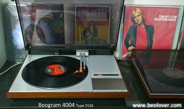
Beogram 4004 Type 5526: Final Test Run

This Beogram 4004 (Type 5526) project has been through a lot. The initial restoration in getting the turntable functioning again was very straight forward and progressed quickly. After that several delays popped up. There were issues with a wobbly sub-platter, restoration of the keypad, polishing the dust cover and repairing the dust cover hinge attachments.

This past week everything finally came together and the Beogram entered its final play testing phase.

I repaired the dust cover hinge mounts using Beolover's reinforcement patches. Here is a sequence of pictures that show the dust cover hing mount repair.


As with most things where old glue needs to be cleaned off I use some GooGone to clean off the Beogram dust cover trim surface before re-attachment.


Like Beolover's repair I used very thin double-sided tape to re-attach the trim.


On both the dust cover and the keypad surface I experimented with new coatings to the surfaces. Spray coating the dust cover is more expensive than the usual polishing method but the resulting dust cover surface is much more durable. It resists scratches and makes cleaning a lot easier. The finish looks good but the clarity of the cover isn't quite as good as the original, non-coated material. So there is a trade off to consider with this option.  I haven't decided which method I prefer so I will need to create some more samples to compare. If the owner of this Beogram 4004 decides he doesn't like the coated finish then no worries, I have a plain polished dust cover I will trade out. Luckily the dust cover on these Beogram 400x turntables is very easy to remove.

Here is the re-assembled Beogram ready for test play.


Since this Beogram will soon be returning to Florida and I am still bummed out about Tom Petty I am playing all the Tom Petty records I can find in my collection.