Featured Post

Beolover SyncDrive: DC Platter Motor Replacement for Beogram 4002 and 4004 (Type 551x and 552x)

Late Beogram 4002 and the 4004 (Types 551x and 552x), which have DC platter motors instead of the earlier synchronous AC motors usually suff...

Saturday, September 30, 2017

Beogram 4002 (5523): Replacement of Degraded Transport Lock Bushings with 3D Printed Replacement Parts

After restoring the arm lowering mechanism of the Beogram 4002 (5523) that is currently on my bench, I took out the circuit boards for restoration. With the circuit boards out, it was a great moment to replace the degraded transport lock bushings with 3D printed replicas. The reason being that fragments of the degraded bushings usually distribute themselves throughout the Beogram enclosure, and some inevitably will go underneath the floating chassis. This poses a problem since the fragments can be large enough to impede the free motion of the chassis, thereby preventing it from insulating the turntable and the tonearm from the enclosure.
The best way to get all the fragments out of the enclosure space is to completely remove the floating chassis, which requires the boards to be out. This shows the chassis still in place:
and the empty enclosure after removal:
Removal requires the disassembly of the transport locks (small parts distributed next to the enclosure - make sure you label the upper and lower nuts as they are counter threaded and note that the longer part of the lock bolts needs to point down). If you look closely you can actually see three bushing fragments that were hidden under the carriage:
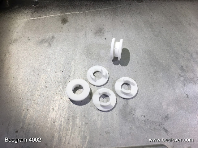
After vacuuming out the enclosure space, it was time to install the replacement lock bushings. Here is a picture of a complete set of the bushings. Each is assembled from two parts:
They are available via the Beolover Shapeways store. To replace all three bushings you'd need to order six parts.

This shows one of the orifices in the sub-chassis where they install:
One of the bushing parts goes in from the bottom:
and the other from the top completing the assembly:
After installing the other two bushings, I re-installed sub-chassis. This shows one of the locks half-way assembled:
and completed:
On to restoring the PCBs!


Beogram 8000: Feel Like Listening to a Record?

The light at the end of the tunnel for a vintage Beogram restoration project is the red glow of light at the end of the fixed arm while the tonearm tracks a favorite vinyl track.

Today is the day for that event with this latest Beogram 8000 from Detroit.

To get to this point I had to reassemble the Beogram parts into the cabinet. I did a little touch up of the inside of the Beogram cabinet with flat black paint. There were some spots where original paint was scraped off and I didn't want any rust to form.


I also had to reinstall the aluminum deck panel on this Beogram as is always the case with these units. I have reverted to using 3M double-sided tape for this as it is the most reliable.


Before suspending the floating chassis with the turntable components to the cabinet I still had to fix the speed sensor bracket mount. I had a spare locking ring to replace the worn, original ring.


Before heading towards the listening room with the Beogram I did a quick check of the platter to arm height. The service manual calls for 23mm and that is what this Beogram measures.


The last thing I did was change out the phono muting relay from the original National relay to a sealed Omron miniature relay.  I used the Beolover adapter board for the National HB2 type relays that he created for the Beogram 4002/4004 turntables. The Omron G6K relay for the Beogram 4002/4004 turntables is a 24 VDC relay. This one on the Beogram 8000 is a 12 VDC relay.


I mounted the replacement relay board assembly where the original relay was installed.


The relay didn't work. It turns out the polarity of the relay coil voltage is different on the Beogram 8000 circuit than the 4002/4004 turntables. So I needed to flip the relay. That turned out to be no problem and solved the relay problem.


I rechecked the phono muting functionality with this new Omron relay and it works great. There is audio with the tonearm is lowered on the record grooves and both channels mute the same when the tonearm lifts.


The Beogram is now to the point I can do some serious record listening. I haven't re-attached the cabinet dust cover or any of the compartment lids. I usually do that as the very last step before shipping the turntable home. That way I can easily open the Beogram back into service position should I find anything that needs adjustment during record play.

Now there is that red glow of the Beogram playing some Marvin Gaye. A nice assist from an MMC-20CL cartridge produces a wonderful listening experience.


Friday, September 29, 2017

Beogram 4002 (5523): Restoration of the Arm Lowering and Tracking Systems

As usual I began the restoration of the Beogram 4002 (5523) that recently arrived at my bench with the restoration of the arm lowering mechanism. At this age the lubricants are often hardened and the tonearm does not lower anymore reliably. This shows the mechanism before I took it apart:
I removed all moving parts
and cleaned them before I re-lubricated and installed everything again. The next step was to lubricate the damper-to-arm linkage pivot point. This requires to remove the sensor arm. This picture shows the arms from the back of the deck:
Removal of two screws at the base allows taking the sensor arm assembly out:
After carefully removing the retaining clip on the pivot shaft (and not loosing the small spring that sits underneath...;-) the linkage can be removed:
After cleaning and re-lubricating I installed the assembly again and adjusted the arm parallelism:
The next step was to replace the tracking sensor light bulb with a LED based assembly. This shows the original tracking sensor light source in place:
Removal reveals the aperture that informs the photo resistors in the base of the tracking sensor about the tonearm angle relative to the carriage travel axis:
This shows the original bulb fixture in comparison with the LED based replacement:
Like all Beolover parts featured on the blog this assembly is available to other enthusiasts. Just send me an email or use the contact form to the right if you are interested. This is how it looks after installation:
It is nice to see that this Beogram 4002 already came with a metal carriage pulley instead of the usual (cracked) plastic pulley.


Sunday, September 24, 2017

Beogram 8000: Preparing for Record Play (UPDATED)

This Beogram 8000 is almost ready for the record listening phase of the testing. There are still a few test milestones to check.

One is to calibrate the tonearm/cartridge tracking force. I like to set the tonearm tracking force to 1 gram and calibrate the arm counter-weight for that force with a typical B&O cartridge attached.  This picture shows the components involved with calibrating the tracking force.


I started out with the B&O tracking force scale but I end up finalizing the adjustment with a digital scale.


The tracking force is set so it is on to the Beogram forward and reverse scanning voltage checks. The controls for the left (forward) and right (reverse) tonearm scanning operate an aperture that passes light onto an LDR device. The amount of light changes the voltage on the device which affects the motor control circuitry responsible for moving the tonearm.

The normal voltage level for the forward LDR and reverse LDR devices should be between 0.6 and 0.7 VDC. Adjustments to that voltage are made by adjusting separate screws for the forward and reverse LDR light apertures.

I like the option to check these LDR voltages after the Beogram is re-assembled in its cabinet. It is easy to pop open the control panel but probing the LDR devices to measure them is difficult at that point. For that reason I attach a small test connector that I can use later for re-adjusting the scanning voltages.


Here is the control panel with the test connector installed. Note that the color coding I use on the test connector matches the corresponding signals on the panel's small ribbon cable. The test connector is a female connector so it can't short out when not being used for testing. Just insert a three-prong test jack and the measurements can be made with a DMM.


Now for some initial measurements.

CORRECTION: The following scanning LDR measurement results have been corrected from the original post.

The reverse direction scanning LDR adjusted nicely within the 0.6 to 0.7 VDC range.

So did the forward scanning adjustment.

No problems with the forward and reverse scanning functions.

The third thing I checked was the Beogram phono muting relay. I have started to see more signs of the original muting relays starting to wear. Sometimes these relays fail completely so it is easy to diagnose. Typically though the relay just starts acting up slowly. It may occasionally fail to switch in and out of muting or it could start exhibiting some noise after closing.

On this Beogram I noticed that the muting relay isn't always completely closing when the phono signals are supposed to be muted.

Here are some pictures that show the problem.

The first picture shows the muting relay open where both channels are playing a music source.
This result looks good and shows the relay is working.


When the tonearm lifts the muting relay closes and the phono signals get shorted. The result should be  both left and right channels muted.  This picture shows that the right channel isn't completely muted.


I tapped on the relay a few times and the muting relay started working again.


The phono muting relay issue will have to be fixed but swapping out the relay is something I can easily do later. It doesn't need to hold up testing the Beogram record play functions.

The last check before record play is to check the tangential arm tracking. To perform this check power is removed from the platter so that it can only rotate manually by hand. The P4 connector is disconnected from the main board to do this.

Note: Unplug the Beogram before unplugging and plugging in any board connections.


The linear tangential arm tracking test calls for setting the Beogram arm onto a Bang & Olufsen Test Record 3621001 track 5. The platter is manually rotated and the rotations counted while observing the tracking motor for movement. When the stylus sets down the tracking motor should begin first moving the arm transport after 2 ± 1 rotations. After that the tracking motor should move on every platter rotation.

I have never been able to find a B&O Test Record 3621001 so I use a couple of records I have found worked well for this adjustment.

Surprisingly, this Beogram 8000 did not require any adjustment to the tracking sensor. It tracked my test records perfectly.


Tomorrow I will re-assemble the Beogram and test play a record.

Thursday, September 21, 2017

Beogram 4002 (5523): A New Arrival - A First Look

A Beogram 4002 (5523) arrived at my bench for some TLC. It was very well packaged except a creative approach towards securing the cartridge for shipping:
Luckily, all went well and the cantilever did not get damaged. So the first thing I did was to secure the cartridge in one of my recently redesigned MMC cartridge boxes:
I will be happy to supply one of these boxes before shipping a Beogram for restoration. They are also available for the newer style MMC1-5 cartridges.

Here is a first look at the cosmetics of the unit:
The aluminum panels are in good condition but the platter is a bit scratched
and the keypad has a worn START key:
This can be fixed by recoating of the keypad surfaces.

The plinth has one damaged edge:
and some marks in the center of the right side panel:

The Plexiglass hood has the often found 'ice rink' (before the Zamboni appears...;-) appearance:
This can be fixed by removing the top layer of the Plexiglass and then polishing it back to a shiny and translucent appearance.

Under the hood the deck appears in original condition:
After I plugged it in and pressed START, the carriage started moving to the set-down point for LPs and the arm was lowered. This was a good sign, however, the platter motor appeared dead. I checked it with an external power supply and it spun normally. This suggests that there is a fault in the motor drive circuit.
Since this Beogram was shipped without tightening the transport locks, the lock bushings completely disintegrated, which was immediately obvious by the brownish-orange fragments accumulated on exposed areas of the sticky side of the blue tape:
They can be replaced by SLS printed replacement bushings available via the Beolover Shapeways store.
In summary, this unit can most likely be brought back close to new condition, possibly to 'like-new' if a pristine replacement platter and plinth were to be obtained from a donor unit.