One is to calibrate the tonearm/cartridge tracking force. I like to set the tonearm tracking force to 1 gram and calibrate the arm counter-weight for that force with a typical B&O cartridge attached. This picture shows the components involved with calibrating the tracking force.

I started out with the B&O tracking force scale but I end up finalizing the adjustment with a digital scale.


The tracking force is set so it is on to the Beogram forward and reverse scanning voltage checks. The controls for the left (forward) and right (reverse) tonearm scanning operate an aperture that passes light onto an LDR device. The amount of light changes the voltage on the device which affects the motor control circuitry responsible for moving the tonearm.
The normal voltage level for the forward LDR and reverse LDR devices should be between 0.6 and 0.7 VDC. Adjustments to that voltage are made by adjusting separate screws for the forward and reverse LDR light apertures.
I like the option to check these LDR voltages after the Beogram is re-assembled in its cabinet. It is easy to pop open the control panel but probing the LDR devices to measure them is difficult at that point. For that reason I attach a small test connector that I can use later for re-adjusting the scanning voltages.

Here is the control panel with the test connector installed. Note that the color coding I use on the test connector matches the corresponding signals on the panel's small ribbon cable. The test connector is a female connector so it can't short out when not being used for testing. Just insert a three-prong test jack and the measurements can be made with a DMM.

Now for some initial measurements.
CORRECTION: The following scanning LDR measurement results have been corrected from the original post.
The reverse direction scanning LDR adjusted nicely within the 0.6 to 0.7 VDC range.
CORRECTION: The following scanning LDR measurement results have been corrected from the original post.
The reverse direction scanning LDR adjusted nicely within the 0.6 to 0.7 VDC range.


No problems with the forward and reverse scanning functions.
The third thing I checked was the Beogram phono muting relay. I have started to see more signs of the original muting relays starting to wear. Sometimes these relays fail completely so it is easy to diagnose. Typically though the relay just starts acting up slowly. It may occasionally fail to switch in and out of muting or it could start exhibiting some noise after closing.
On this Beogram I noticed that the muting relay isn't always completely closing when the phono signals are supposed to be muted.
Here are some pictures that show the problem.
The first picture shows the muting relay open where both channels are playing a music source.
This result looks good and shows the relay is working.
This result looks good and shows the relay is working.

When the tonearm lifts the muting relay closes and the phono signals get shorted. The result should be both left and right channels muted. This picture shows that the right channel isn't completely muted.

I tapped on the relay a few times and the muting relay started working again.

The phono muting relay issue will have to be fixed but swapping out the relay is something I can easily do later. It doesn't need to hold up testing the Beogram record play functions.
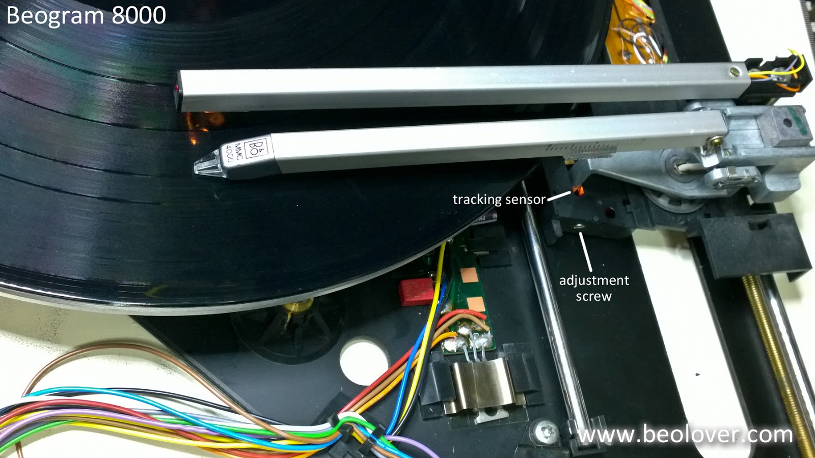
The last check before record play is to check the tangential arm tracking. To perform this check power is removed from the platter so that it can only rotate manually by hand. The P4 connector is disconnected from the main board to do this.
Note: Unplug the Beogram before unplugging and plugging in any board connections.

The linear tangential arm tracking test calls for setting the Beogram arm onto a Bang & Olufsen Test Record 3621001 track 5. The platter is manually rotated and the rotations counted while observing the tracking motor for movement. When the stylus sets down the tracking motor should begin first moving the arm transport after 2 ± 1 rotations. After that the tracking motor should move on every platter rotation.
I have never been able to find a B&O Test Record 3621001 so I use a couple of records I have found worked well for this adjustment.
Surprisingly, this Beogram 8000 did not require any adjustment to the tracking sensor. It tracked my test records perfectly.


Tomorrow I will re-assemble the Beogram and test play a record.
The last check before record play is to check the tangential arm tracking. To perform this check power is removed from the platter so that it can only rotate manually by hand. The P4 connector is disconnected from the main board to do this.
Note: Unplug the Beogram before unplugging and plugging in any board connections.

The linear tangential arm tracking test calls for setting the Beogram arm onto a Bang & Olufsen Test Record 3621001 track 5. The platter is manually rotated and the rotations counted while observing the tracking motor for movement. When the stylus sets down the tracking motor should begin first moving the arm transport after 2 ± 1 rotations. After that the tracking motor should move on every platter rotation.
I have never been able to find a B&O Test Record 3621001 so I use a couple of records I have found worked well for this adjustment.
Surprisingly, this Beogram 8000 did not require any adjustment to the tracking sensor. It tracked my test records perfectly.

Tomorrow I will re-assemble the Beogram and test play a record.


