This is a follow up to my initial post about my BeoloverRPM device that can be used to quantify RPM stability and fluctuations in Beogram 400x and 8000x models (essentially all models that have 24 radial rubber strips on the platter).
I realized that a main application of the BeoloverRPM device is precision adjustment of the RPM in the analog 400x models. With a currently estimated precision of better than 0.03% the Beolover RPM device substantially outperforms the standard calibration discs that use the grid frequency from a light bulb, and also the 'AC motor Beogram way' of adjusting the motor frequency with an oscilloscope. Both of these 'traditional' methods yield maybe a precision of 1%. Similar errors arise when using a test record and a 3.3kHz or 1kHz tone...oscilloscopes are just not that great when it comes to measuring frequency precisely. A better way is to use a spectrum analyzer with a test record, but even this is fraught with significant errors due to non-centered records and noise issues.
In difference to these analog methods the BeoloverRPM device precisely measures the time that it takes for the black ribs to pass by the optical sensor, and microcontrollers are very good at measuring time precisely due to their quartz oscillators and their ability to do things very quickly. In fact it mimics the way the 800x models measure the RPM for their feedback control mechanism. And they are very precise at keeping 33.33 RPM over a long period of time. The BeoloverRPM is based on processor interrupts generated by the optical sensor, which essentially means that the error of the measurement comes mainly from the optical performance of the sensor. This remaining error is dealt with by doing a statistical real-time analysis of the measured data. The generated standard deviation output allows monitoring the quality of the measurement and/or the performance of the motor.
Using the BeoloverRPM device for RPM adjustment requires that it can be securely mounted on a Beogram while it is in service position so one can access the base RPM trimmers for the base RPM adjustment. This meant I had to come up with a different design of the system. I realized that it is best to clamp it directly on the metal frame of the enclosure. This allows to be close to the platter while giving a high mechanical stability to ensure a stable sensor position relative to the platter (correct distance is very important for the accuracy of the sensor).
Here are a few impressions of the current state of affairs. This shows the system in action:
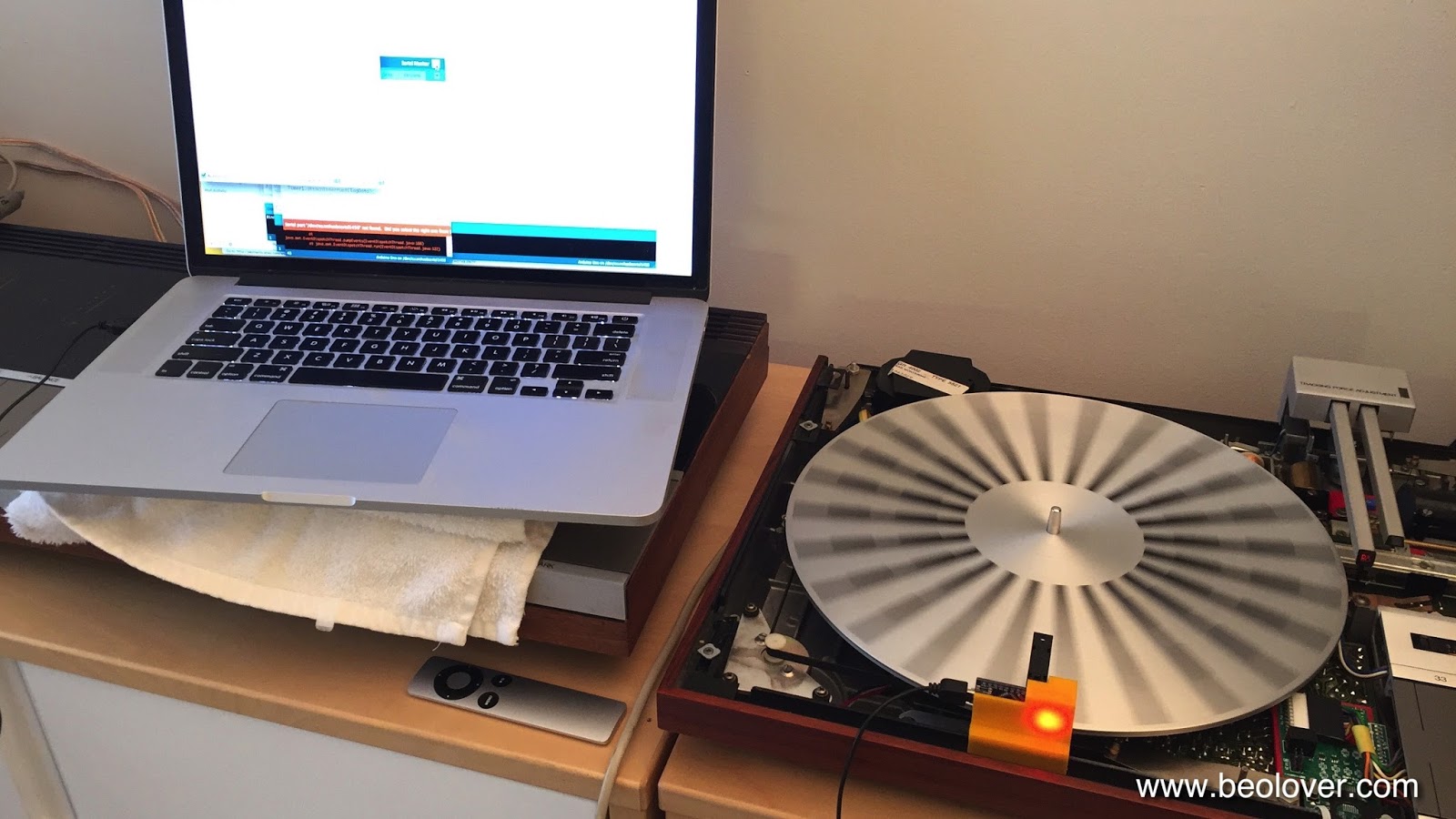
Doesn't the power LED look pretty as it shines through he orange plastic print??...;-) The device hooks up to a laptop via a standard mini-USB flex cable. It simply bangs its data through the serial port in ASCII, which allows to use any terminal software on the computer to do the readout. I use the Arduino IDE's serial monitor. The device is now based on an Arduino Nano board with a CH340 USB interface. This makes it necessary to install the appropriate USB driver for this chip. Other than that it is 'plug and play'. The main advantage of this re-design, however, is that there is no more cable between microcontroller and sensor. This makes it much more straight forward with regard to assembly and use stability.
Here are a few detail shots. This shows the final design in front of the preliminary design studies of the plastic cradle (it is notoriously difficult to make a 3D print of a small part to fit something else precisely, and usually only extensive trial and error results in a satisfying fit):

I designed a spring clamp at the bottom for sticking it on the Beogram frame since the 4000 has a thinner frame than the later 4002/4 models. That way the cradle fits on both types:


The small slot is for pushing out the circuit board in case one needs to extract it. It makes a pretty solid press-fit with the cradle. Here is a detail photo how it clamps onto the Beogram frame:

A very solid fit for a precision RPM measurement! I want my customers' vinyls to play at the correct pitch! I am thinking about a 'consumer version' based on my initial design, which could have a direct LCD (or even a 'B&O style red LED 7-segment 4 digit back to the 1984 future style'...;-) display readout, so one could do a RPM check once in a while (yes, there is indeed some drift over time and depending on temperature in these classic analog designs) and compensate with the user accessible RPM trimmers on the control panel for continued precision listening enjoyment. This is Beolove!
Hello, I'm very interested in the Beogram RPM device.
ReplyDeleteCan it be used for the Beogram TX2 and for 33.3 and 45 RPM?
What would the device cost if there is still this to buy?
Best regards from B & O fan Wilfried from Heilbronn / Germany