Featured Post

Beolover SyncDrive: DC Platter Motor Replacement for Beogram 4002 and 4004 (Type 551x and 552x)

Late Beogram 4002 and the 4004 (Types 551x and 552x), which have DC platter motors instead of the earlier synchronous AC motors usually suff...

Tuesday, March 21, 2017

Beomaster 8000: Ready for Some Bench Testing

Ever since I restored the power supplies, output amplifiers and preamplifiers on this Beomaster I have been exercising it with an iPod through TP1 & TP2 as well as playing the FM radio. The receiver has continued to play and sound very good as I added the restored FM boards, Filter & Tone Control board and the Microcomputer board. Now it is time to start putting the Beomaster back together and do some bench testing.

As I started the reassembly I tried the remote control for the first time. No functionality. So I will have to dive back in to the power supply board where the remote control receiver lives to see what is wrong. But first I decided to continue with some initial bench testing. I have been anxious to take some measurements and I don't see any reason to let the remote control problems delay that right now.

Before using any test equipment I decided to run a functional check pairing the Beocord 9000 that I restored earlier. These two will be returning together to their owner soon and I wanted to see how they play together for the first time since their restoration.


I used an original seven pin DIN cable for TP1 to connect it to the Beomaster. Pressing the play button on the Beocord turns puts the Beomaster into TP1 play mode as expected. Pressing the standby (off) button on the Beomaster turns both units off (and into standby mode). So they are communicating well. The Beocord also sounds great. In a later bench test I will add one of my Beogram 8002 turntables to the mix so I can both check out the phono input and do some recording on the Beocord.

Next up for this testing session though is to use my QA400 spectrum analyzer to check the Beomaster 8000 from its source input (TP1) to its output amplifiers (Speaker 1).


Beolover has featured some measurements before from his QA400. It is a nice little bench analyzer that uses a PC to do all of its analysis. The connection to the computer is via a USB cable and software on the PC sets up the tests performed. Up until now I have only done low voltage level testing with this type of setup because the inputs to sound card devices and this QA400 are limited to the ±5 volt range. Connecting to the power amplifier outputs was not doable. I picked up some differential voltage probes by the QA400 manufacturer that will allow me to measure higher voltages. For this Beomaster source-to-speaker test I will use a couple of fixed 8 ohm loads to simulate speakers and connect the differential probes to the dummy speaker connectors.


The probe is powered by batteries and has a BNC connector to run a coax cable to the QA400 input terminal. For some reason I could not get my test setup working as I wanted with both differential probes connected at the same time (one for the right channel and one for the left channel). With both probes connected I see some undesirable noise at 60 Hz from my house line voltage. So far swapping cables and probes doesn't solve the problem. The only thing that works is using one of the probes on one channel at a time. Then there isn't any 60 Hz noise present. So I performed my tests one channel at a time switching the speaker connection to the Beomaster. The measurement results look pretty good. I won't post all of the frequencies I checked (400Hz, 1kHz, 5kHz, 10kHz, 15kHz) but here is the 1kHz test on the left channel. I tested with the analyzer set to unweighted and A-weighted.


Here is a 5kHz test on the right channel.


Viewing the distortion numbers and sound to noise level readings at a few select frequencies was nice to see. This Beomaster sounds really good but I like to see some sort of measurable result besides my own ears.

Now it is back inside to see what is wrong with the remote control receiver.


Sunday, March 19, 2017

Beogram 4002 (5513): RPM Trimmer Illumination Very Low

After restoring the PCBs of this Beogram 4002 (5513) it was time to address the very low background illumination of the 33 and 45 RPM trimmer scales. I removed the RPM trimmer panel and put it on the bench:
After removal of the light shields the bulbs can be accessed:
A closer examination revealed that the bulbs had been replaced at some point with non-spec units resulting in the too low light intensity. As usual, I replaced these bulbs with my SMD LED based implants:
Like all my parts they are available to other enthusiasts. Just send me an email or use the contact form on the right. They are direct drop in replacements for the light bulbs:
The design allows for putting the covers back in place:
The combination red and green LEDs of the replacements generate a warm incandescent-like light that not only looks authentic, but also properly illuminates the red scale hands of the RPM trimmer displays:
Beolovely! These displays are back in business!


Saturday, March 18, 2017

Beogram 4002 (5513): Restoration of PCBs and Reservoir Capacitors

After rebuilding the tonearm and drive carriage systems of this Beogram 4002 (5513), it was time to address the electronics. The first step is always to replace all electrolytic capacitors and RPM trimmers and relay to ensure trouble free operation in the decades to come. This shows the main PCB in its original condition:
And after replacing the components:
This shows the RPM control section in detail:
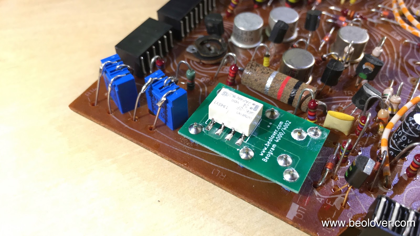
The replacement relay is a Beolover design that matches the footprint of the original Siemens relay:
These replacements re available to other enthusiasts. Just send me an email or use the contact form on the right. On to the reservoir capacitors. This shows the original dual capacitance unit:
This is a unique design containing two common grounded capacitors with 4700uF and 1000uF capacitances. These capacitors are not made anymore and so they need to be replaced with two individual units. To keep things organized, I designed a 3D printed fixture that holds things in place:
and from the back:
It fits precisely into the same spot and the original mounting clamp can be used to hold the assembly in place. This assembly is also available.
The final step was to replace the relay and single electrolytic capacitor on the output PCB. This shows the original board:
And with the replacement parts:
The red switch is an upgrade that I designed. It allows to connect system and signal grounds in case there are humming issues (mainly when connecting the Beogram to an amplifier with RCA inputs). 


Friday, March 17, 2017

Beogram 4002 (5513): Restoration of Arm Lowering and Tracking System

After the first evaluation of this Beogram 4002 my starting point of its restoration was as usual rebuilding the arm lowering and tracking systems. My customer already did the cleaning and lubricating of the damper and solenoid linkages, so all that was left was to remove the linkage between the damper and the tonearm. This requires taking out the sensor arm assembly. This shows the arms from the back:
Taking out the sensor arm requires removal of two screws at its base:
Then the linkage can be removed:
After cleaning and lubricating the bearing I put the arm back together and bolted it back onto the carriage. Then it was time to adjust the arms orthogonal to the carriage tracks and parallel to each other:
Once this was done, I installed my LED based tracking sensor light source replacing the incandescent lightbulb that originally illuminates the tracking sensors. This shows old and new light sources in direct comparison. The LED is in exactly the same spot as the filament of the bulb:
On the back of the LED unit the blue trimmer is used to adjust the light intensity. This makes it much more straight forward to adjust the tracking sensor sensitivity:
This shows the original light source in place:
And the replacement:
The final step of the carriage restoration was to clean the threaded rod that advances the carriage and put a new pulley on. This shows the original cracked and glued on (shudder!) plastic pulley:
After breaking it loose in pieces from the rod the new precision turned aluminum pulley could be installed:
Very Beolovely, if you ask me! If you wanted to upgrade your 400x to a pulley like this, send me an email or use the contact form to the right. I'll be happy to get you in touch with the Master of Pulleys! By the way: All my parts featured on this blog are available to other enthusiasts, too! On to restoring the electronics!


Monday, March 13, 2017

Beogram 4000: Restoration of AC Motor

A while ago I realized that the AC motor of the Beogram 4000 that I restored started making distinct knocking noises in sync with the pulley rotation when I played it. This was a sign that the Oilite brass bearing needed an oil re-infusion. Oilite bearings are porous brass bearings that get factory oil infused under vacuum. Over time the oil is dispensed onto the shaft of the motor and from there into the motor housing. This means that after a certain run time the bearings need to be replaced or re-infused. If you have a food vacuum sealer, this can be done with a mason jar. Here are a few impressions of my process:

First the motor needs to be removed
Then the two rivets that hold it together need to be pressed or drilled out:
This shows the motor opened up:
and a peek at the bearing in the bottom part:
For the record, this shows the arrangement of a spring and washers on the motor shaft:
Since after removal of the coils there is only metal left, one can simply put the entire enclosure into oil and pull a vacuum:
The usual air bubbles formed as the air escaped the brass pores. After about 24 hrs the process came to a halt, indicating that the bearings were again full of oil.

Since the rivets had to be destroyed for opening the motor, I replaced them with two 3D printed parts that hold M3 nuts enabling to put the pitch adjustment screws back in:
This shows the motor back in the enclosure:
After this procedure the motor was quiet again.


Beomaster 8000: Tackling the Lid Damper

On these last two Beomaster 8000 and Beocord 9000 projects the owner had to have the damper devices for the lids removed as they had begun to leak fluid. This appears to be a common problem with the grease used by B&O on these series of components (Beomaster 8000, Beomaster 6000, Beocords 8000-9000).  Of course these these devices are thirty plus years old now so that has to be taken into account.

The Beocord 9000 I worked on doesn't have its damper anymore so I will replace it with a spare from another Beocord. The Beomaster 8000 damper is still intact although removed from the unit.

Here is a picture of the dampers I have available for this project and some of my future projects. The damper in the center has the most leakage of the bunch. Also shown are an original lid lever for the Beomaster 8000 and a 3D replacement lever that Beolover can provide. While the damper devices are the same between the various Beosystem components of this series, the levers are not. The Beomaster 6000 and Beocords require a different size lever. In the picture below the lever out of this Beomaster 8000 is not original. It is a pretty good hand-made replacement carved out of plastic. However, the plastic has become quite brittle and starts to break with the slightest pressure applied. The other lever is the Beolover 3D printed replacement. That is what I will use on this Beomaster.


This next picture shows a few of these dampers opened up. The two on the far right still functioned to some extent. The others no longer did much as their grease is pretty much gone. Two of the dampers had their plastic mounting clips melted in place as an attempt to keep the device sealed. I had to cut them open and they were pretty empty so the grease leaked out anyway. When I rebuild these my plan is to use black hot glue. I think it will hold secure enough yet allow disassembly in the future.


The next to last damper device on the right is the only one that had an additional, thin, white washer installed. I don't know if that is original or something that was added later by someone.

Here is a closer up picture of the dampers that still had functioning grease. Next to them is the replacement damping grease I will use. The thing to figure out next is how much grease is required for these dampers to operate correctly. Should the entire housing be filled? I hope not. One tube of this special damping grease is about $50 USD so it is quite an expensive product. However, it is made for the purpose of damping and claims it will not break down under high temperature.


Here is a cleaned out damper with the Nyogel applied. It is ready to be sealed up.


Beomaster 8000: Display Board Rebuilt

The reworked Beomaster 8000 display modules have spent enough time on the test jig. All of the new SMD LEDs passed the burn-in test so I can finish up the last circuit board in this restoration project...the display board.

Here is the board with its original components. The arrows designate the board components that will be replaced: The four display modules, the four light bulbs, a 10uF electrolytic capacitor and a 4.7uF tantalum capacitor. The four light bulbs will be replaced with Beolover's direct replacement LED component. That means also removing four 220Ω resistors (R34, R36, R38 and R40). As with all of the other Beomaster 8000 board restoration, I reflow the solder on all of the board connectors.


Here are the lamps and resistors alongside the new Beolover indicator light modules.


Here we go, the last board re-installed in the Beomaster...and everything works. An expected result but always a relief to actually see.


Note that it is always difficult to get a good photograph of the LED displays the way they really look. If I turn down the ISO and shutter speed I can get a better representation of the displays but then everything else is too dark. The display segments all look uniform and will match the Beocord 9000 I did earlier.

This Beomaster is about ready to close back up for the bench, system testing phase. However, I do need to rebuild the lid damper before I can put this unit back together so it is time to start that repair.

Update: Here are some better photos of the new displays in the Beomaster. They look quite good I think. I followed Beolover's basic restoration method of blacking out any sources of stray light from the LED using various materials like black vinyl tape and black hot glue.